If you are one of those people who would like to spend your well-earned summer vacation in the comfort of a hill resort but are worried about your potted companions back home, then a plant watering system is what you need. The project, “Automatic Plant Watering System Circuit,” immediately waters the plant once the soil becomes dry. By adding timer circuits and other components, we can enhance the flexibility of this project and make further improvements, allowing it to operate automatically for the duration set by the timer.
Circuit Description of Automatic Plant Watering System: –
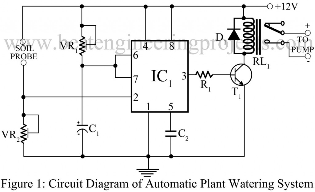
The circuit diagram of the automatic plant watering system is shown in Figure 1 and is built around one of the most popular integrated circuits (ICs), the IC555. It also includes a pump and other passive components. As the soil dries up, its resistance increases, causing the voltage at pin 2 of IC555 to fall below 1/3 Vcc. This activates the trigger comparator, causing the output to go high and switch on the pump. The output remains high for the time interval set by VR1 and is given by
The equation evolved for calculating the time interval is given below:
Where R is the resistance connected between the power supply and pins 6 and 7 of the timer IC 555, and is in ohms. C is the capacitor connected between pin 6 and ground, and it is specified in microfarads.
For adjusting the time interval, we are using a variable resistor instead of a fixed resistor.
Let’s assume we use a capacitor of value 470 uF and a fixed variable resistor at the center, say 500 k-ohm, the time will be calculated as:

When the soil becomes dry enough to trigger the water pump, the automatic plant watering system is activated for approximately 4 minutes and 30 seconds.
The sensitivity of the circuit is adjusted by adjusting the variable resistor VR2.
The soil probe is designed using any metal; however, during development, one key consideration must be taken into account, namely, the material of the soil probe. When we supply voltage to the metal probe, it begins to react with soil moisture, and as a result, rusting and deposition occur. To slow down the rusting and deposition process, stainless steel must be used.
Check out other interesting projects posted on bestengineringprojects.com
- Ultrasonic Water Level Meter
- Water Level Indicator Circuit using 7-Segment
- Water Level Indicator Circuit
- Water Level Controller Using NE555
PARTS LIST OF AUTOMATIC PLANT WATERING SYSTEM
| Resistors (all ¼-watt, ± 5% Carbon) |
| R1 = 1 KΩ
VR1, VR2 = 1 MΩ |
| Capacitors |
| C1 = 470 µF, 16V (Electrolytic Capacitor)
C2 = 0.01 µF (Ceramic Disc) |
| Semiconductors |
| IC1 = NE555 (Timer IC)
T1 = SL100 (medium Power NPN Transistor) D1 = 1N4001 (Rectifier Diode) |
| Miscellaneous |
| RL1 = 12V, 100Ω Relay |
Do you have the PCB layout of this one? It would be a good help for me regarding my term paper please answer quick …
What is the value of vr1. My motor get on when the power supply is on but get unaffected when soil prob conduct or not
The value of variable resistor VR1 is already listed in parts list.
VR1 = 1M-ohm
Sir can you please tell how relay is connected
Hi, please refer to the link https://bestengineeringprojects.com/how-to-make-relay-switch-circuit/
This may help you.
When we are giving motor pump teriminals at pin 3,The model is working but when we are giving the motor pins at collector terminal and at relay.even if we take wire from pin3 and connect it with motor it is not working.How it is possible to stop the motor after sometime because we are continuously giving trigger when soil is dry.please tell what is the problem with connection of motor with relay.
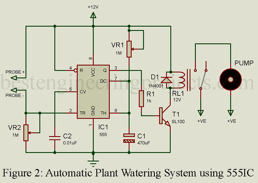
Please refer to figure 2 for the proteus design for a clear concept.
Thanks.
Soil probe is that soil moisture sensor or just to wire inserted into soil
You can use a probe of soil sensor (only probe) or any metal. But be careful while choosing the metal for the soil probe. Because when we supply voltage to metal it starts to react with soil moisture. So, a stainless steel probe is a better choice than a soil sensor probe.
How to control the operating time of a water pump?
To control the operating time of the water pump, adjust the resistor (VR1) and capacitor (C1) values in the 555 timer circuit. The pump ON time is set by the formula:
T = 1.1 × R × C (in seconds).
Please suggest another transistor instead of SL 100.