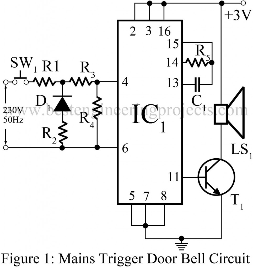
Door bell system is probably one of the earliest electronics project. Large number of projects has followed the series, each with different components and different sound effects. The projects published till now were either completely battery operated or were mains based. On doing so, the project consumed more power form a single source and sometimes didn’t even operate for desired limit of time. Here we have tried to reduce the problem to some extent by publishing the project “Mains Trigger Musical Door Bell Circuit”.
This unique Mains Trigger Musical Door Bell Circuit utilizes both sources, it uses mains to trigger the IC and then the entire circuit components drain supply from the battery included in this circuit. Thus the circuit is not solely dependent up on one particular source and can enjoy benefits from both sources.
Circuit Description of Mains Trigger Music Door Bell
The heart of the circuit mains trigger door bell is musical IC UM3482 around which the entire circuit is fabricated. It is then accompanied by a transistor, diode and some other passive components. Using the combination of components like resistor R1, R2 and diode D1, the ac mains supply is fed to the pin 4 of IC1 so as to trigger the circuit. To avoid the case of leakage, resistor R4 is included in the circuit to block unwanted trigger and prevent wastage of battery supply.
Check out various other door bell project project in bestengineeringprojects.com
- Door Bell Circuit
- Light and Touch Operated Music Door Bell
- Alarm Circuit | Door Bell Circuit
- 12 Tones Door Bell
PARTS LIST OF MAINS TRIGGER MUSIC DOOR BELL CIRCUIT
| Resistors (all ¼-watt, ± 5% Carbon) |
| R1 = 220 KΩ
R2 = 33 KΩ R3 = 22 KΩ R4, R5 = 100 KΩ |
| Capacitor |
| C1 = 33 pF (Ceramic Disc) |
| Semiconductors |
| IC1 = UM3482 (Music IC)
T1 = BC147 (general purpose npn transistor) D1 = 1N4007 (Rectifier Diode) |
Miscellaneous |
| SW1 = Push – To – On switch
LS1 = 8 Ω loudspeaker |
