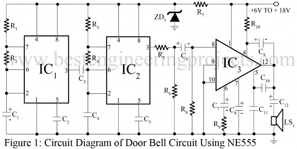
This project describes the constructional and working details of a door bell circuit. The door bell circuit presented here is of 2-notes (modulated sound) type and delivers about 4-watt Musial power at 12 volt.
While using it as a door bell circuit, 6V DC supply is enough, which can be derived either from dry battery cells or a battery eliminator. The door bell circuit is flexible enough to work off right from 6V to 18V supply, without change of any component in the circuitry. However, it is important to use a speaker of the right rating. The speaker should be rated one watt for 6V supply, 5 watt for 12V, and 7 watt for 18V.
Circuit Description of Door Bell Circuit
The door bell circuit works around three ICs. While IC1 and IC2 are for tone generation, IC3 works as a power amplifier. Supply to the system is derived from 12V battery and fed directly to IC3. IC1 and IC2 receive the regulated supply of 5.1 volts derived through zener diode ZD1 and resistor R7.
The master tone of approx. 400 Hz generated by IC2 is fixed by R3, R4 and C4. The ratio of R3 and R4 fixes the ‘softness’ in the sound output. Modulation of the master tone is governed by IC1, which runs a 1Hz. The frequency fixing components are R1, R2 and C1. With the values used for R1 and R2 almost equal space ratio (square wave) is obtained at pin 3.
Coupling between IC1 and IC2 is provided by capacitor C3. IC1 connects capacitor C3 in parallel to C4 during the ‘on’ period and disconnects it during the ‘off’ period. Value of C3 is so chosen that when it is connected in parallel to C4 through IC1, the output of IC2 is around 200 Hz. Since IC1 is running at 1 Hz, the resultant output of IC2 is 400 Hz for half second and 200 Hz for the next half second, and so on. Capacitor C2 and C5 are the functional components for IC1 and IC2. Modulated output of IC2, available at its pin 3 is attenuated through the potential divider comprising R5 and R6, and fed to the amplifier is formed around IC3, and the components around that IC are its functional component.
While R9 fixes the input sensitivity, C10 and C11 fix the frequency response of the amplifier. Output of IC3 available at its pin 12 is fed to the loudspeaker through coupling capacitor C12.
Check out various other door bell project project in bestengineeringprojects.com
- Mains Trigger Musical Door Bell Circuit
- Light and Touch Operated Music Door Bell
- Alarm Circuit | Door Bell Circuit
- 12 Tones Door Bell
PARTS LIST OF DOOR BELL CIRCUIT
| Resistor (all ¼-watt, ± 5% Carbon) |
| R1 = 1 KΩ
R2, R3, R8 = 100 KΩ R4 = 4.7 KΩ R5 = 10 KΩ R6= 470 Ω R7, R10 = 100 Ω, 1W R9 = 10 Ω |
| Capacitors |
| C1 = 4.7 µF,6V (electrolytic capacitor)
C2, C5 = 0.01 µF (ceramic capacitor) C3 = 0.02 µF (ceramic capacitor) C4 = 0.03 µF (ceramic capacitor) C6 = 5 µF, 6V (electrolytic capacitor) C7 = 500 µF,16V (electrolytic capacitor) C8, C9 = 100 µF,16V (electrolytic capacitor) C10 = 1.5 KpF (polyester capacitor) C11= 5.6 kpF (polyester capacitor) C12 = 1000 µF,25V (electrolytic capacitor) |
| Semiconductors |
| IC1, IC2 = NE555 timer IC
IC3 = TBA810S (Audio Amplifier IC) ZD1 = 5.1V, 1W zener diode |
| Miscellaneous |
| LS1 = 4-Ω (metal-cone type) loudspeaker
Heat-sink for IC3 |

Great project!!
I choose it as my project ,bur there is some questions:
What is the purpose of IC3 because i couldn’t find it so may be you can suggest for another one with the same purpose
Thank you
IC3 (TBA810s) is an audio amplifier, you may find in most electronic store. As it is use to drive a loudspaker (power amplifier) you can replace it with any power amplifier ic with necessary modification. LM1875 or one of TDA20xx will do fine.