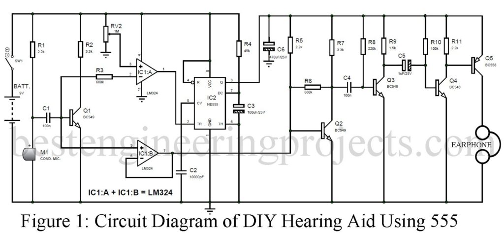
The general circuit of Hearing Aid available over the internet used a normal transistorize circuit thus it consumes more power. So, here we are concentrated to design a circuit that consumes less power, DIY Hearing Aid Circuit using 555.
For that, the circuit present here of DIY Hearing Aid Using 555 has an automatic triggering mode which consumes 96 mA at the time of amplifier trigger or you can say when sound is detected else it consumes only 6 mA which is very less. Other than less power consumption the circuit has an advantage like the user can select sensitivity as well as the amplifier’s on-time duration. We have also posted Hearing Aid Circuit using operational amplifier LM358.
Circuit Description of DIY Hearing Aid using 555
The circuit of DIY Hearing Aid using 555 is shown in figure 1. The components used in DIY Hearing Aid are most common and easily available on market. A quad op-amp IC (LM324) has four individual op-amp circuits integrated into it, out of four we had only used two op-amps (one as a comparator whereas the other as a unity follower). A timer IC NE555 is configured in monostable mode with timer constant components R4 (resistor) and C2 (capacitor). The value we have selected for these components is 4.9 or we can say 5 seconds on the timer.

A microphone is used to detect a sound and convert it into an electrical signal which needs further amplification. For amplification, we used a pre-amplifier as well as an amplifier circuit. Pre-amplifier circuit is built around transistor T1. When sound is detected by the microphone it converts it into an electrical signal and is fed to the base of transistor T1. The amplifier output is available at the collector which is fed to inverting input (pin 2) of IC1:A which is compared with the reference voltage available at the non-inverting input (pin 3) of IC1:A (configured in comparator mode). When the pulsating voltage at the collector is more in comparison to the reference voltage at pin 3 the output at pin 1 of IC1:A become low. This low output trigger timer IC2 (NE555). The output from pin 3 is high which provides a power source for the amplifier section.
One output from the microphone is also fed to the non-inverting input of IC1:B which is configured in unity follower mode as its inverting pin is connected to the output (pin 7). This is done to overcome the problem of impedance mismatch. The output from pin 7 is given to the base of transistor T2 which amplify the weak signal and is fed to the next stage of the amplifier (T3. T4 and T5 respectively). A PNP transistor (T5) is used in the last stage which drives the earphone.
BEP NOTE: The earphone used in the circuit DIY Hearing Aid using 555 must be mono-type earphones with a voice control facility.
PARTS LIST OF DIY HEARING AID CIRCUIT USING 555
| Resistor (all ¼-watt, ± 5% Carbon) |
| R1, R5, R11 = 2.2 KΩ
R2, R7 = 3.3 KΩ R3, R6 = 680 KΩ R4 = 49 KΩ R8 = 220 KΩ R9 = 1.5 KΩ R10 = 100 KΩ VR1 = 1 MΩ PRESET |
| Capacitors |
| C1, C4 = 0.1 µF (Ceramic Disc)
C2 = 0.01 µF (Ceramic Disc) C3 = 100 µF/25V (Electrolytic Capacitor) C5 = 1 µF/25V (Electrolytic Capacitor) C6 = 470 µF/25V (Electrolytic Capacitor) |
| Semiconductors |
| IC1 = LM324 (Quad op-amp)
IC2 = NE555 (Timer IC) T1, T2 = BC549 (NPN General Purpose Transistor) T3, T4 = BC548 (General Purpose NPN Bipolar Junction Transistor) T5 = BC558 (General Purpose PNP Transistor) |
| Miscellaneous |
| M1 = Condenser Microphone
SW1 = ON/OFF Switch 9V Battery Earphone |
after fixing the circuit up on board its given distoted noise
Good summarized notes