In this article we will discuss about decoder and encoder IC, its key parameter and its application. Let’s start with its description
Description Decoder and Encoder IC
Decoders are essentially an arrangement of logic elements that are combined to change from one digital code to another. The term “decoder” is most frequently used but, depending on the point of view, the term “encoder” is equally correct.
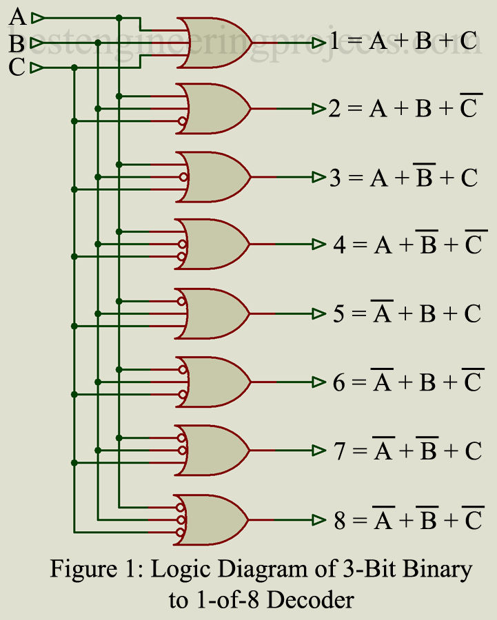
Figure 1 shows the logic diagram of a 3-bit binary-to-1-of-8 decoder. The inputs A, B, and C can represent any logic function, and the output 1 through 8 will then provide the addition or the logic OR function of these three inputs. In order to produce the complement of the input functions, the OR circuits have inverters at the inputs indicated by the small circle. As an example, output 4 is
.
If the input A, B, and C were each logic 1s, output 4 is would be 1. If A = 0, B = 1, C = 1, then output 4 is 0. A close look at the logic diagram of figure 1 shows that it represents the conversion from a 3-bit binary to an octal number. Output 1 represents the octal number 7 and output 89 represents the octal number 0.
The most widely used types of decoders are presented in the following pages. In addition to these standard ICs, special purpose decoders are around in some digital logic systems. Decoders are available in all of the commonly-used digital families, such as CMOS, TTL, ECL, etc.
Key Parameters of Decoder and Encoder IC
The electrical characteristics are essentially the same as those of the particular digital IC family.
- Maximum Power Dissipation: The maximum power dissipated by the IC when in operation. This will vary according to the digital IC family and also according to the number of stages or logic elements used.
- Quiescent Current: The current used by the entire IC when no operations take place. This will vary according to the digital IC family and according to the number of logic elements used.
- Noise immunity: The relation of the noise amplitude as a percentage of the power supply voltage. This parameter usually depends on the digital IC family.
- Propagation delay time: The time requires from input to output. While this depends, to some extent, on the digital IC family, the complexity of the logic gating and the number of stages between input and output are also important factors.
- Control signals: Some decoders have means of enabling all or parts of the inputs or outputs. Special input and output terminals to permit cascading decoders are also available in some decoders.
Applications
Decoders are used in digital systems whenever it is necessary to change from one code to another. Specific applications are presented for the different decoders described in following articles.
- BCD to Decimal Decoder
- BCD to 7-Segment Decoder
- Excess-3 (Gray) to Decimal Decoder
- 8-bit Priority Encoder
- Binary to 2 of 8 Decoder
- 16-Key Encoder Decoder
- BCD to Binary and Vice-Versa Decoder
- Manchester Code Encoder and Decoder

NICE WORK