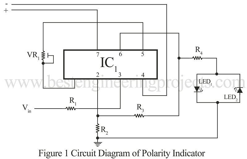
Now, here is another basic electronic project using the most versatile operational amplifier IC 741 “DC Volt Polarity Indicator”. Using the project DC volt polarity indicator one can know the positive and negative polarity of DC volt. This project is very useful for electronics hobbyists to check either battery polarity or polarity at the output of the DC source. The circuit present here is so simple that even electronics beginners can understand how the circuit works.
Circuit Description of DC Volt Indicator Using IC 741
The heart of the circuit DC volt polarity indicator is op-amp 741, which is here used in Non-inverting mode. The power supply is given to the circuit through the positive (+) and negative (-) lines. DC Polarity to be tested is connected to Vin pin (pin 3) of IC1 via resistor R1. If positive DC volt is given to Vin pin, DC positive volt has appeared at output pin (pin 6) and if negative volt is connected to Vin pin, DC negative volt has appeared at output pin (pin 6).
The output of IC1 is connected to LED1 and LED2 via resistor R4 which is used here as a current limiter. Glowing LED1 (RED LED) indicates negative DC volt and glowing LED2 (GREEN LED) indicates positive DC volt.
PARTS LIST OF DC VOLT POLARITY INDICATOR USING IC 741
|
Resistor (all ¼-watt, ± 5% Carbon) |
|
R1 = 100 KΩ R2 = 680 Ω R3 = 100 KΩ R4 = 560 Ω VR1 = 10 KΩ |
|
Semiconductors |
|
IC1 = 741 (Operational Amplifier) LED1 = RED LED LED2 = GREEN LED |

What is the benefit of variable resistor and when vin is zero what led is work and why? Tank you
Dear sir , what is the value for input voltage?
What voltage you give it to opamp