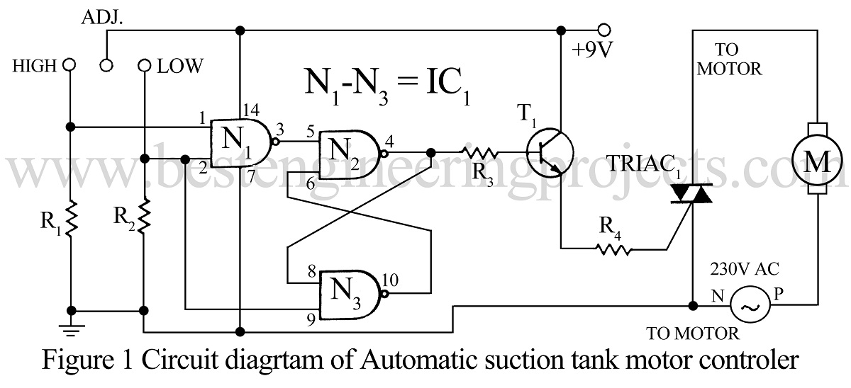
Many of us use water pumps for drawing water from an underground tank. Whenever the water level in the tank goes low we have to switch ‘off’ the motor and when it reaches a high level we have to switch ‘on’ the motor. The circuit automatic suction tank motor controller given here solves this problem.
|
The truth table for the digital circuit of automatic suction tank motor controller |
||||
|
Condition |
H |
L |
Y |
Remark |
|
Empty tank |
0 |
0 |
0 |
|
|
Water is filled up to ‘L’ |
0 |
1 |
0 |
|
|
Full tank |
1 |
1 |
1 |
The motor is ‘on’ |
|
Waterfalls below ‘H’ |
0 |
1 |
1 |
Still, the motor is ‘on’ |
|
Again tank is empty |
0 |
0 |
0 |
Off |
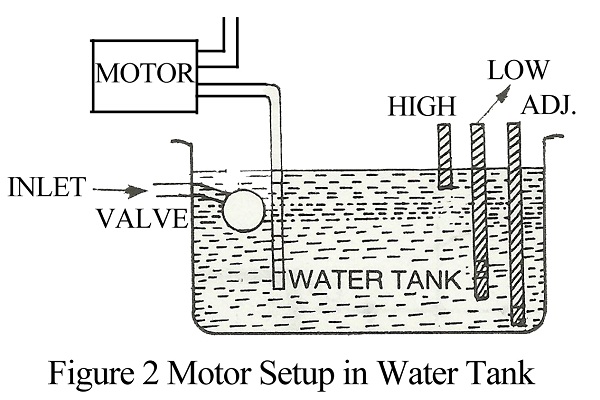
The circuit of the automatic suction tank motor controller uses an RS flip-flop. The arrangement of sensor probes in the tank is shown in the motor setup in the water tank diagram.
It is evident from the truth table that the circuit identifies the point after which the higher level becomes ‘0’ from ‘1’ and keeps the motor ‘on’ even if the higher level is at zero states. This is because of the property of RS flip-flop under the ‘no change’ condition.
Three-way cables can be used as three sensors, wound on a wooden stick, with their insulation cut at one end. Power may be derived from a suitable power supply or battery.
Check out other motor driver and speed controller projects posted on bestengineeringprojects.com
- BLDC Motor Driver Circuit
- AC Motor Speed Controller Circuit Using AT89C51
- Low Voltage Motor Speed Regulator
- 3 Phase Induction Motor Starter
- DC Motor Control Circuit
PARTS LIST OF AUTOMATIC SUCTION TANK MOTOR CONTROLLER
|
Resistor (all ¼-watt, ± 5% Carbon) |
|
R1, R2 = 1MΩ R3 = 10 KΩ R4 = 470 Ω |
|
Semiconductors |
|
IC1 = CD4011 (Quad NAND Gate IC) TRIAC1 = 4A, 400V (TRIAC) T1 = BC147 (General Purpose NPN Transistor) |

