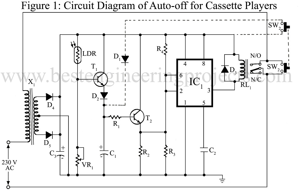
Most common stereo cassette players have an auto-stop deck mechanism but do not have the auto power-off function. The circuit is meant for cassette players having an operational voltage of 12 V DC with the facility of LED type VU meter. When the sound signal stops, the power is automatically switched off after a delay of approximately 30 seconds.
Circuit Description of Auto-off Cassette players
With sound present, the LEDs of VU meter emits light. The LDR on receiving light from LEDs gives a high pulse to transistor T1which charge capacitor C1. The slow discharging of the capacitor provides a delay. Hence different values of C1 give delays of different durations. Charging and discharging of the capacitor results in an exponential signal which is passed through IC1 NE555 (working as Schmitt trigger) to convert it into a digital signal for proper functioning of the relay.

For setting and construction of the circuit Auto-off for cassette players:
- Take connections of only first LED of the VU meter. For arrangement of mounting of LDR and LED together, place them face to face and warp with 3 – 4 folds of black paper.
- In some cassette players, the circuit shown in dotted line is not required. So first try without this circuit.
- For setting 1-megaohm pot, turn it to zero resistance and connect the LED to emit light. Then connect the main circuit to 12V. Now start increasing the resistance of pot until the relay clicks ‘on’. In this circuit the approximate value of VR1 is 100KΩ.
- A good relay should be used with covered mechanism placed far away from the main circuit of auto-off for cassette players.
PARTS LIST OF AUTO-OFF FOR CASSETTE PLAYER
|
Resistor (all ¼-watt, ± 5% Carbon) |
|
R1 = 15 KΩ R2 = 470 Ω R3, R4 = 100 KΩ VR1 = 1 MΩ (Linear) |
|
Capacitors |
|
C1= 100 µF/16V (Electrolytic Capacitor) C2 = 0.01 µF (Ceramic Capacitor) C3 = 1000 µF/16V (Electrolytic Capacitor) |
|
Semiconductors |
|
IC1 = NE555 T1, T2 = BC148B D1 – D4 = 1N4001 |
|
Miscellaneous |
|
X1 = 230V Primary To 12V-0V-12V 1 Amp. Sec. Centre-Tap Transformer RL1 = 12V DC 100 Ω Relay SW1, SW2 = Ganged Push-To-On Switch LDR |