Hertz Antenna with Parasitic Element | Antenna Arrays
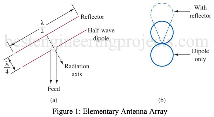
The most elementary antenna arrays are shown in Figure 1. It consists of a simple Hertz half-wave dipole and a non-driven (not electrically connected) half-wave element located a quarter wavelength behind the dipole. The non-driven element is also termed a parasitic element since it is not electrically connected.
The dipole radiates electromagnetic waves with the usual bidirectional pattern. However, the energy traveling toward the parasitic element, upon reaching it, induces voltages and currents but incurs a 180° phase shift in the process. These voltages and currents cause the parasitic element to also radiate a bidirectional wave pattern. However, due to the 180° phase shift, the energy traveling away from the driven element cancels with that from the driven element. The energy from the parasitic element traveling toward the driven element reaches it in phase and causes a doubling of energy propagated in that direction. This effect is shown by the radiation pattern in Figure 1(b). The parasitic element has also been termed a reflector since it effectively “reflects” energy from the driven element. Notice that this simple array has resulted in a more directive antenna and thus exhibits gain concerning a standard half-wavelength Hertz antenna.
Let us consider why the energy from the reflector gets back to the driven element in-phase and thus reinforces propagation in that direction. Recall that the initial energy from the driven element travels a quarter wavelength before reaching the reflector. This is equivalent to 90 electrical degrees of phase shift. An additional 180° of phase shift occurs from the induction of voltage and current into the reflector. The reflector’s radiated energy back toward the driven element experiences another 90° of phase shift before reaching the driven element. Thus, a total phase shift of 360° (90° + 180° + 90°) results so that the reflector’s energy reaches the driven element in phase.
Yagi-Uda Antenna
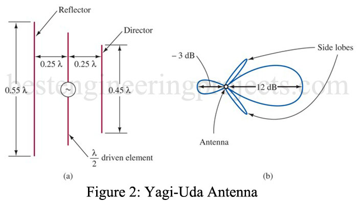
The Yagi-Uda antenna consists of a driven element and two or more parasitic elements. It is named after the two Japanese scientists who were instrumental in its development. The version is shown in Figure 2(a) has two parasitic elements: a reflector and a director. A director is a parasitic element that serves to “direct” electromagnetic energy since it is in the direction of the propagated energy concerning the driven element. The radiation pattern is shown in Figure 2(b). Notice the two side lobes of radiated energy that result. They are generally undesired, as is the small amount of reverse propagation. The difference in gain from the forward to the reverse direction is defined as the front-to-back ratio (F/B ratio). For example, the pattern in Figure 2(b) has a forward gain of 7 dB and a -1-dB gain (actually, loss, since it is a negative gain) in the reverse direction. Its F/B ratio is therefore [7 dB – (-1 dB)], or 8 dB.
This Yagi-Uda antenna provides about 7 dB of power gain concerning a half-wavelength dipole reference. This is somewhat better than the approximate 3-dB gain of the simple array shown in Figure 1. In practice, the Yagi-Uda antenna often consists of one reflector and two or more directors to provide even better gain characteristics. They are often used as HF transmitting antennas and as VHF/UHF television receiving antennas.
The analysis of how the radiation patterns of these antennas result are rather complex and cannot be simply accomplished, as was done for the simple array shown in Figure 1. More often than not, the lengths and spacings of the parasitic elements are the results of experiments rather than theoretical calculations.
Driven Collinear Array
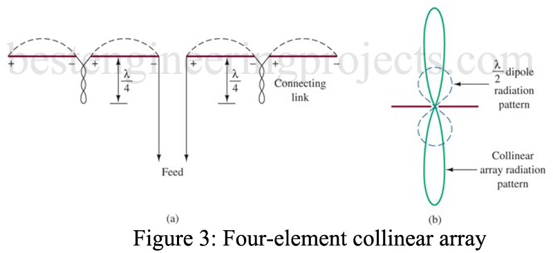
A driven array is a multielement antenna in which all of the elements are excited through a transmission line. A four-element collinear array is shown in Figure 3(a). A collinear array is any combination of half-wave elements in which all the elements are placed end to end to form a straight line. Each element is excited so that its fields are all in phase (additive) for points perpendicular to the array. This is accomplished by the length of transmission line (a
twisted pair) between the elements on both sides of the feed point. They are twisted so that the fields created by the line cancel each other to minimize losses.
The radiation pattern for this antenna is provided in Figure 3(b). Energy off the ends is canceled from the spacing (cancellation) of elements, but reinforcement takes place perpendicular to the antenna. The resulting radiation pattern thus has gain concerning the standard Hertz antenna radiation pattern shown with dashed lines in Figure 3(b). It has gain at the expense of energy propagated away from the antenna’s perpendicular direction. The full three-dimensional pattern for both antennas is obtained by revolving the pattern shown about the antenna axis. This results in the doughnut-shaped pattern for the Hertz antenna and flattened doughnut shape for this collinear array. The array is a more directive antenna (smaller beamwidth). Increased directivity and gain are obtained by adding more collinear elements.
Broadside Array
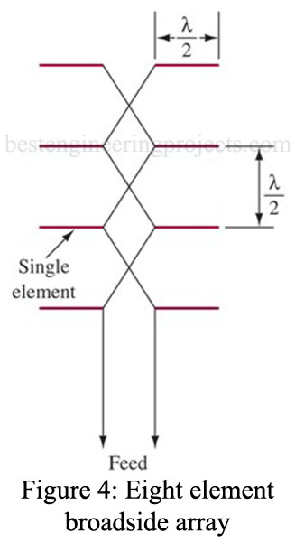
If a group of half-wave elements is mounted vertically, one over the other as shown in Figure 4, broadside antenna arrays are formed. Such an array provides greater directivity in both the vertical and horizontal planes than the collinear array. With the arrangement shown in Figure 4, the separation between each stack is a half wavelength. The signal reversal shown in the connecting wires puts the voltage and current in each element of each stack in phase. The net resulting radiation pattern is a directive pattern in the horizontal plane (as with the collinear array) but also a directive pattern in the vertical plane (in contrast to the collinear array).
Marconi Array | Antenna Arrays
You have probably noticed that standard broadcast AM transmitters usually utilize three or more Marconi antennas lined up in a row with equal spacing between them. The radiation pattern of a single Marconi antenna is omnidirectional in the horizontal plane, which may be undesirable due to interference possibilities with an adjacent channel station or due to geographical population density patterns. For instance, it doesn’t make sense for a New York City station to beam half of its energy to the Atlantic Ocean. By properly controlling the phase and power level into each of the towers, virtually any radiation pattern desired can be obtained. Thus, the energy that would have been wasted over the Atlantic Ocean can be redirected to the areas of maximum population density.
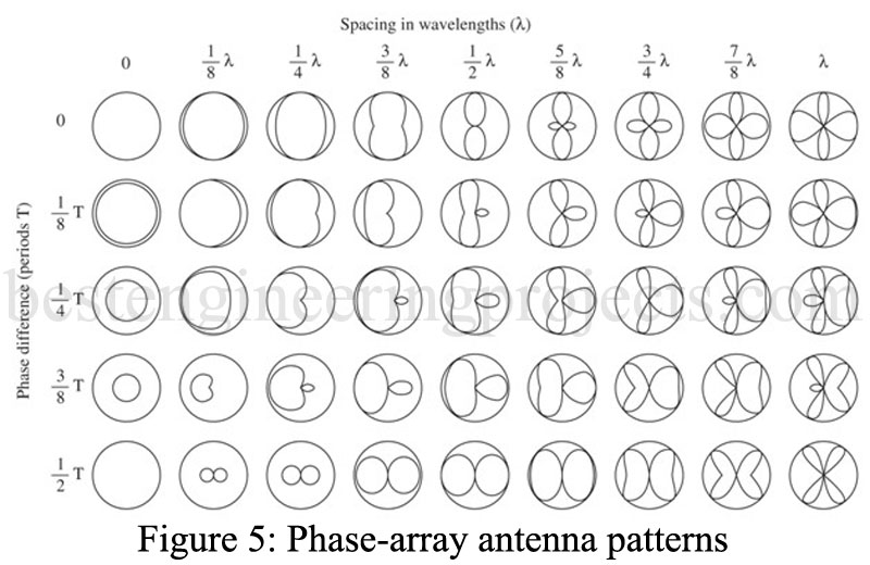
This arrangement is called a phased array since controlling the phase (and power) teach element results in a wide variety of possible radiation patterns. A station may easily change its pattern at sunrise and sunset because increased skywave coverage at night might interfere with a distant station operating at about the same frequency. To give an idea of the countless radiation patterns possible with a phased array, refer to Figure 5. It is the radiation for just two vertical antennas with variable spacing and input voltage phase. The patterns are simply the vector sum of the instantaneous field strength from each antenna.
