What is a Directional Coupler?
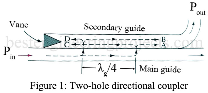
The two-hole directional coupler consists of two pieces of waveguide with one side common to both guides and two holes in this common side. Its function is analogous to directional couplers used for transmission lines. The sections may be arranged physically either side by side or one over the other. The directional properties of such a device can be seen by looking at the wave paths labeled A, B, C, and D in Figure 1.
Waves A and B follow equal-length paths and thus combine in phase in the secondary guide. If the spacing between holes is , waves C and D (which are of equal strength) are
or 180° out of phase and thus cancel. Therefore, if the field within the main guide consists of a superposition of incident and reflected waves, a certain fraction of the wave moving left to right will be coupled out through the secondary guide, and the same fraction of the right-to-left wave will be dissipated in the vane. The wave traveling from right to left causes this energy to be canceled in the secondary guide’s output due to the 180° phase shift caused by the
path difference of its two equal components through the two coupling holes. This type of coupler is frequency-sensitive since the spacing between holes must be
or an odd multiple thereof. The addition of more holes properly spaced can improve both the operable frequency range and directivity. This is known as a multi-hole coupler.
Thus, we see that a directional coupler transfers energy from a primary to an adjacent-otherwise independent-secondary waveguide for energy traveling in the main guide in one direction only. The energy that flows toward the left in the secondary guide is absorbed by the vane in Figure 1, which is a matched load to prevent reflections.
The ratio of Pout and the incident power, Pin, is known as the coupling:
….(1)
We now can understand that a directional coupler can distinguish between the waves traveling in opposite directions. It can be arranged to respond to either incident or reflected waves. By connecting a microwave power meter to the output of the secondary guide a measure of power flow can be made. The coupling is normally less than 1% so that the power meter has a negligible loading effect on the operation in the main guide. By physically reversing the directional coupler, a power flow in the opposite direction is determined, and the level of reflections and SWR can be determined.
