Waveguide Tees are microwave devices that are used to either divide the power of waveguides or combine the power of waveguides. Waveguide Tee is named after the English alphabet “T” and is of three types named according to their design.
Types of Waveguide Tee
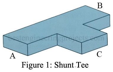
- Shunt tee or E-plane tee [Figure 1]: A shunt tee is so-named because of the sidearm shunting the E field for TE modes, which is analogous to voltage in a transmission line. It can be seen that if two input waves at arms A and B are in phase, the portions transmitted into arm C will be in phase and thus will be additive. On the other hand, an input at C results in two equal, in-phase outputs at A and B. Of course, the A and B outputs have half the power (neglecting losses) of the C input.
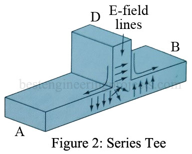
- Series tee or H-plane tee [Figure 2]: If you consider the E field of input at D, you should be able to visualize that the outputs at A and B will be equal and 180° out of phase, as shown. Once again, the two outputs are equal but are now 180° out of phase. The series tee is often used for impedance matching just as the single-stub tuner is for transmission lines. In that case, arm D contains a sliding piston to effect a short circuit at any desired point.
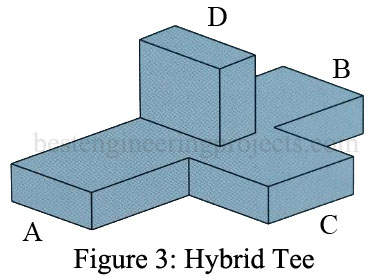
- Hybrid or magic tee [Figure 3]: This is a combination of the first two tees mentioned and exhibits properties of each. From previous consideration of the shunt and series tees, it can be seen that if two equal signals are fed into arms A and B in phase, there will be cancellation in arm D and reinforcement in arm C. Thus, all the energy will be transmitted to C and none to D. Similarly, if energy is fed into C, it will divide evenly between A and B, and none will be transmitted to D. The hybrid tee has many interesting applications.
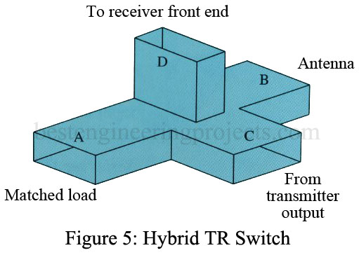
A typical hybrid tee application is illustrated in Figure 13. It is functioning as a transmit/receive switch (TR switch), which allows a single antenna to be used for both transmission and reception. The transmitter’s output is fed into arm C, where it splits between the A and B outputs, with virtually no power going to the sensitive receiver at D. When when the antenna receives a signal at B, energy is sent to the receiver at D as well as to arms A and C. The low received power does no damage to the powerful transmitter output. The matched load at A is necessary to prevent reflections.


