The circuit described here is a Priority Lamp Circuit which gives priority in switching. Switches SW1 to SW4 is a push-to-off type or push-button type, as desired. Normally, pushing off any switch will turn ‘on’ the corresponding relay, i.e. pushing of SW1 enables the NPN transistor T1, and hence relay RL1 operates. The logic section of is designed to get a controlled high output. The pressing of one switch disables the operation of all switches and results in priority in switching. In normal cases, all switches are closed and all relays are in an ‘off’ state. When two switches are pressed in one step, it checks priority and one relay turns ‘on’ in Priority Lamp Circuit.
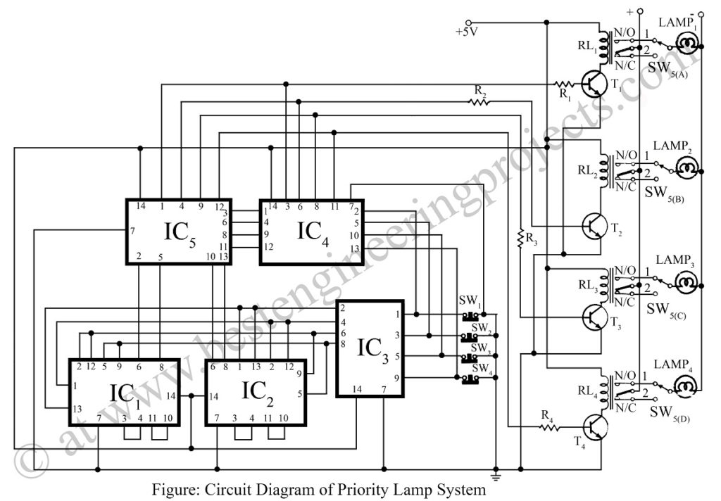
The circuit of Priority Lamp Circuit comprises five ICs. IC1, IC2, and IC4 (7408) are quad 2-input AND gates. IC3 (7432) is a quad 2-input OR gate. IC5 (7404) is a hex inverter that can be replaced by IC 7400 with some specification modifications. The feedback loop between output and input lines of IC4 and IC5 gives controlled high output for one relay.
Select SPDT relay for dual-mode operation for priority in ‘on’ and ‘off’ for the connected lamps as shown in the circuit diagram of Priority Lamp Circuit.
The input and output lines of the digital section can be connected to the other digital circuit to detect the input line from which the first high occurs. It is also used to make a non-interrupted multichannel system. When anyone channel is in a working state the other channels are automatically disabled in Priority Lamp Circuit.
NOTE: – In the switch SW5 (a–d) position 1 is for priority-ON, 2 is for priority-OFF
PARTS LIST OF PRIORITY LAMP CIRCUIT
|
Resistor (all ¼-watt, ± 5% Carbon) |
|
R1 – R4 = 2.2 KΩ |
|
Semiconductors |
|
IC1, IC2, IC4 = 7408 IC3 = 7404 IC5 = 7432 T1 – T4 = SL100 |
|
Miscellaneous |
|
SW1 – SW4 = Push – To – Off Switchs SW5 (a–d) = 4 Poles 2Ways Switch RL1 – RL4 = 5V, 100Ω SPDT relay Lamp1 – Lamp4 |