Preamplifier circuits, especially those having a high input impedance and those handling very small signals (and hence having high gain), are prone to be troublesome. All these are tested circuits, but one must emphasize the need for care while rigging up a preamplifier circuit. A preamplifier circuit is used to meet one or more of the following requirements:
Signal amplification: Raw signal from the source generally lies in the region of 0.5mV to 100mV, whereas signal strength required at the input of the power amplifier for rated output is of the order of 350 mV to 1V. A preamplifier circuit is used to boost the signal sufficiently to drive the power amplifier.
Impedance matching: For optimum performance, different sources of signals have different output impedance. It is not feasible to alter the input impedance of the power amplifier to suit the requirement of the signal source. Generally, a power amplifier has a low to medium impedance.
Equalization: While recording on tapes and discs, certain frequencies are emphasized while others are attenuated. During playback, the amplifier must reverse this deliberately-introduced nonlinearity. To achieve this, the preamplifier circuit is required to provide different gains at different frequencies. This is termed equalization.
Additional facilities: Very often, the preamplifier circuit is expected to provide such additional facilities as tone controls and various types of filters – to modify the response to make up for deficiencies in the listening area and to cater to the personal taste of the listener.
A preamplifier circuit must carry out all these faithfully, without contributing excessive noise and distortion. Hence, in a preamplifier circuit, at least in its low-signal-level stages, it is necessary to use low-noise devices.
From the above, it is fairly clear that a preamplifier circuit could be a simple circuit or a relatively complex interconnection of simple circuits. Depending upon one’s interest in audio, and of course, on one’s budget, a preamplifier circuit could mean different things to different people. Hence, it is not possible to give just one or two circuits that will meet everyone’s requirements. Rather, as has been done in the section on the preamplifier circuits, several circuits should be given. It is then up to the constructor to analyze his requirements and suitably interconnect one or more circuits to meet them.
Precautions must be taken to prevent unintentional feedback which could lead to oscillations and instability. Proper decoupling of the different stages must be carried out and screening procedures may have to be adopted to avoid hum pick-up. Ground loops must be avoided at all costs.
Preamplifier Circuit List
Name of the Preamplifier Circuit |
Circuit Sample |
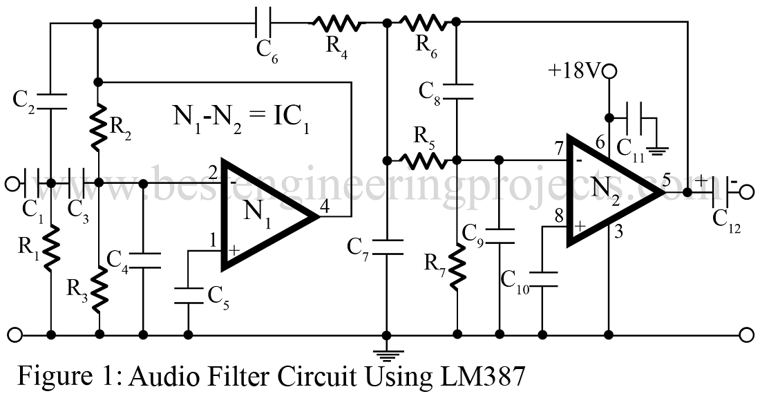
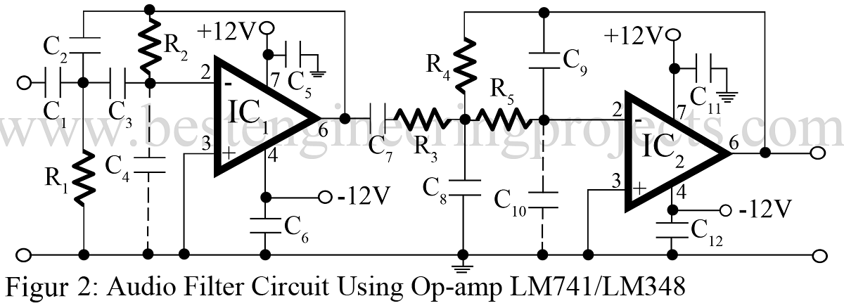
1. Audio Filter Circuit |
 |
 |
|
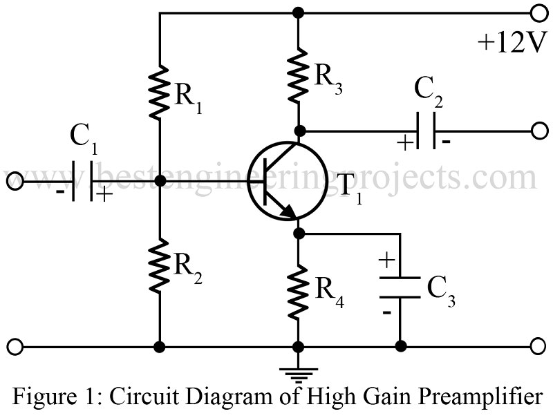
2. High Gain Preamplifier Circuit Using Single Transistor |
 |
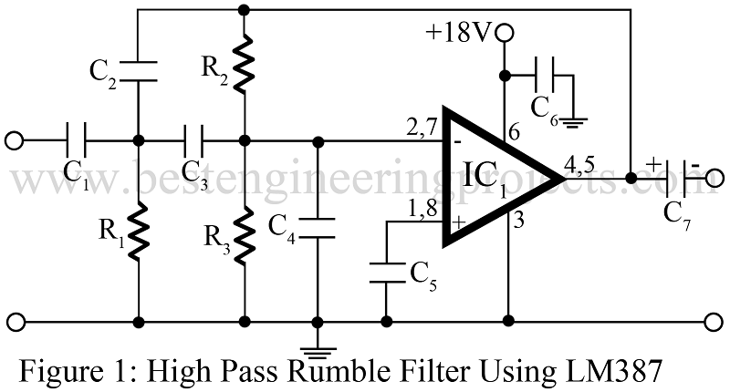
3. High Pass Filter Circuit | Rumble Filter |
 |
 |
|
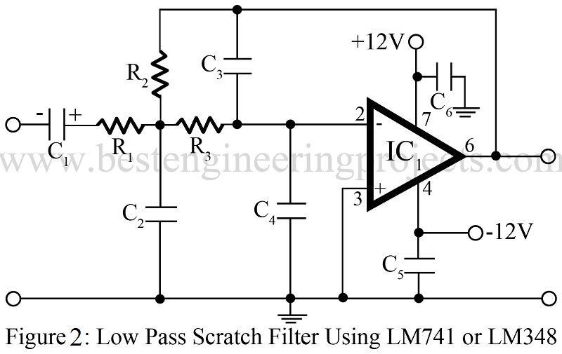
4. Low Pass Filter Circuit | Low Pass Filter Design |
 |
 |
|
5. Preamplifier for Ceramic Pick-up |
 |
6. Simple Preamplifier Circuit Using Single Transistor |
 |
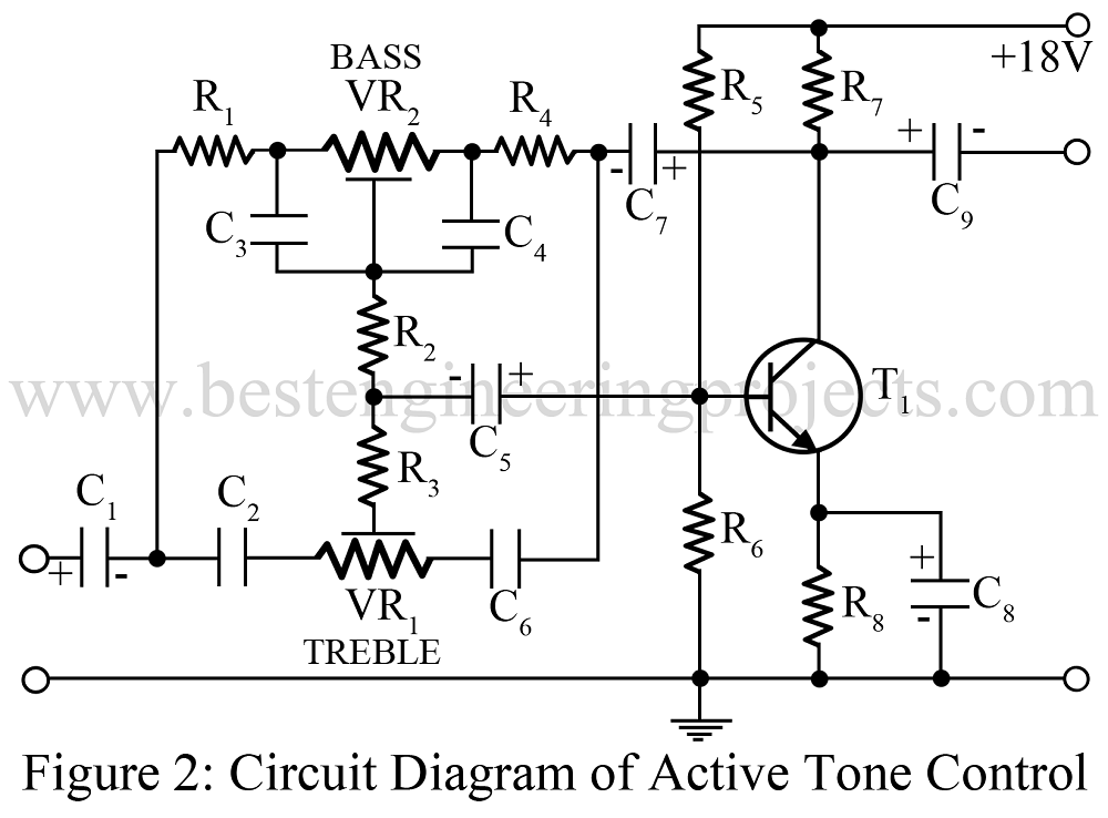
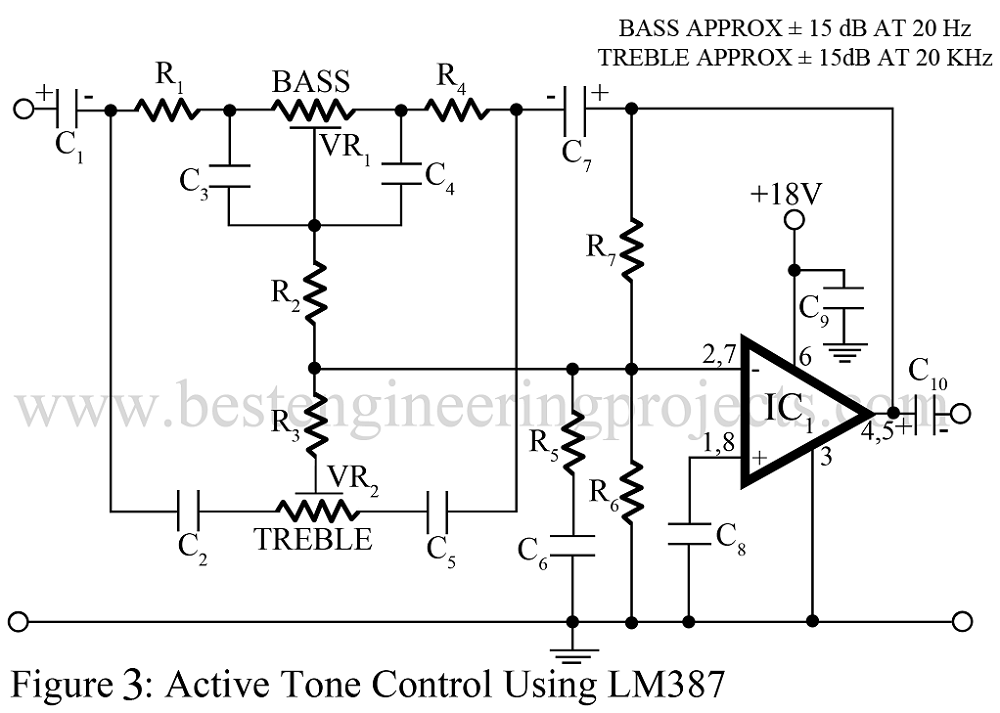
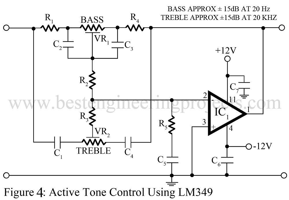
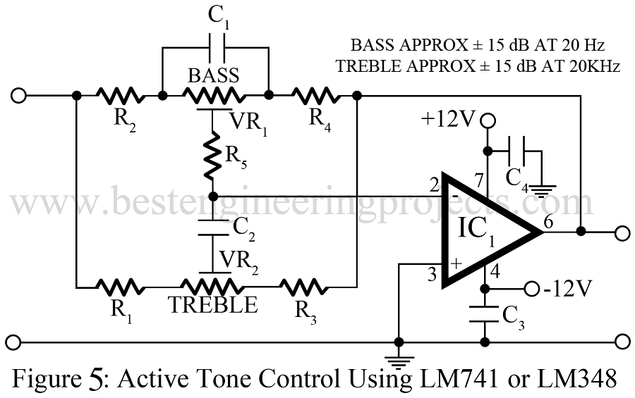
7. Tone Control Circuit (Active and Passive) |
 |
 |
|
 |
|
 |
|
 |
|
8. Bass Treble Circuit |
|
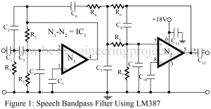
9. Speech Filter Circuit |
 |
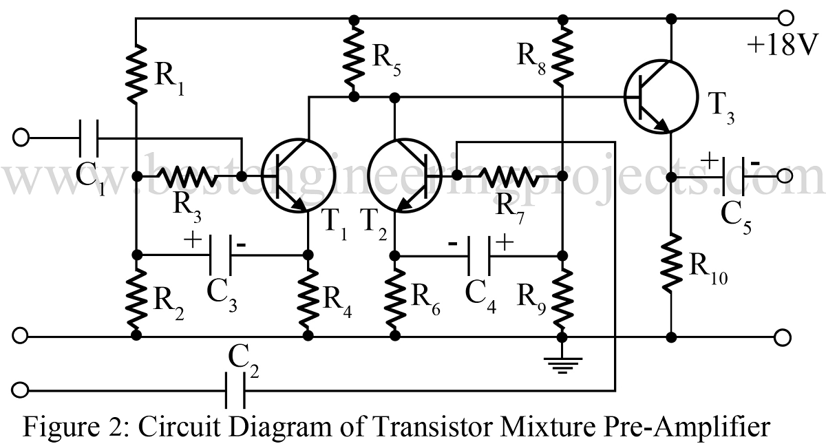
10. Audio Mixer Circuit |
 |
 |
|
 |
|
 |
