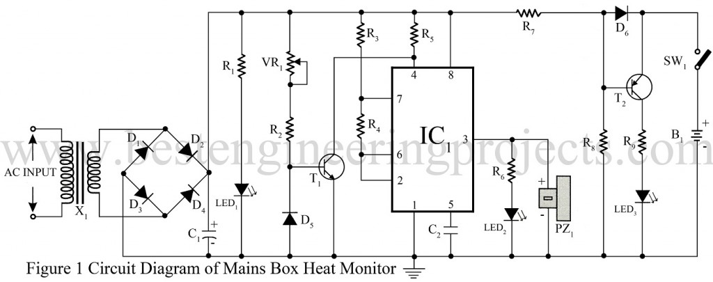
Here is a simple circuit mains box heat monitor for sensing high temperature due to overheating. This circuit helps to prevent disasters caused by only sparking in the mains box due to any fault as a short circuit overloaded. This circuit is so designed that it also automatically switches on a bright white LED (LED3) in case of power failure. This light is sufficient to check the mains box wring or fuses in darkness.
Circuit Description Mains Box Heat Monitor
The circuit is built around a timer IC, a sensor, and two transistors. The input AC mains is stepped down by using a 0-9v 500mA transformer and rectified by using a bridge rectifier built using four diodes D1 through D4. The rectified voltage is further filtered by using 1000 µF of the capacitor (C1) to smoothen the voltage and bypass the ripple. The output is given to LED1 through resistor R1 to indicate the power-on condition. Resistor R1 is used here as the correct limiter.
Diode D5 is a germanium diode which is here acts as a temperature sensor and is used in reverse bias mode. The resistance of diode D5 is high at normal temperature areal as a result transistor T1 conducts to hold pin 4 of IC1 in a low state. Potentiometer VR1 is used here to adjust the sensing capability of the circuit.
Timer IC (IC1) is configured here as an astable multivibrator and generates frequency when the temperature around diode D5 rise due to overheating of the fuse. The resistance of diode D5 is decrease when temperature rise and transistor T5 stop conducting and this enables IC1. The output of IC3 is given to LED2 through resistor R6 for visual indication. A piezo buzzer (PZ) is connected parallel to LED1 as shown in the circuit diagram for audio indication.
The emergency light circuit is built around a PNP transistor (T2). It is powered by a 9V rechargeable battery. The battery B1 is also charged constantly via forwarding bias diode D6 in mains on condition. The forward bias of diode D6 results in reverse biasing of transistor T2 and thus white LED (LED3) is off. Similarly in absence of a mains transistor T2 is forward bias and lights up the LED (LED3)
The circuit beeps once when power fails and again when power resumes.
BEP NOTE: Diode D5 should be placed close to the fuse and the LED3 should be directed towards the fuse such that the maximum lights fall on the fuse. In BEP LAB we test the circuit by putting the hot tip of soldering iron near diode D3. The piezo buzzer PZ1 will sound to indicate the high temperature.
PARTS LIST OF MAINS BOX HEAT MONITOR
|
Resistor (all ¼-watt, ± 5% Carbon) |
|
R1 = 330 KΩ R2 = 100 K KΩ R3 = 1 K KΩ R4 = 56 K KΩ R5 = 4.7 KΩ R6 = 220 Ω R7 = 47 Ω/0.5W R8 = 470 KΩ R9 = 150 KΩ |
|
Capacitors |
|
C1 = 1000 µF, 25V (Electrolytic Capacitor) C2 = 0.01 µF (Ceramic Disc) |
|
Semiconductors |
|
IC1 = NE555 (Timer IC) T1 = BC548 (General Purpose Silicon NPN Transistor) T2 = BC558 (General Purpose Silicon PNP Transistor) D1 – D4 = 1N4007 (Rectifier DIode) D5 = 1N34 (Germanium Diode) D6 = 1N4001 (Rectifier Diode) |
|
Miscellaneous |
|
X1 = 230V AC primary to 0-9V 500mA, Secondary Transformer PZ1 = Piezo Buzzer |

Awesome