Listening bug? What is that? Is it what strikes your head, the first time you see this title? Well, allow us to clear your confusion. Listening bug is a resemblance to that concept improves the quality of sound we hear.
Input sound collected by the condenser microphone with high-sensitivity is supplied to the Listening Bug Circuit and adjustable sound gain is obtained at its output which improves the quality of sound for obvious reasons. Now, people can hear everything smoothly without risk of interruption and no talks will be missed. For effective implementation of the circuit, we recommended using a 6V (4X1.5V) battery. Previously, we had already posted listening bug circuit using op-amp 741 IC
Circuit Description of Listening bug Circuit using op-amp LM386
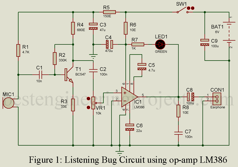
As stated in above paragraph, there is no vital component in this Listening bug circuit as a chief element. It incorporates ideas of using simple discrete components to perform amplifying operations and thus enhance the quality of sound. Figure 1 depicts the circuit diagram of the listening bug project. At the input terminal, you can see a transistor BC547 (T1) and signal amplifier circuit attached to T1. At that point also called preamplifier phase, the sound signal collected by the condenser microphone (MIC1) is amplified to a certain level by the combination of T1 and few relatable components. Here resistor R5 and capacitor C3 combinedly built up a decoupling network that supplies preamplifier phase with a regular supply voltage. In the next phase, that signal is pushed through capacitor C2 (100nF) and volume control VR1 (10-kilo-ohm log) as input to pin 3 of IC LM386N (IC1).
One must note the fact that audio amplifier IC1 employed in this circuit works best with power supply range in between 4-15V DC. You might have been thinking why IC LM386N? It is because of low quiescent current and this IC is best pick for portable applications powered with few batteries. The IC is fabricated in a standard 8-pin DIL package.
In the second phase of this project, capacitor C2 projects output signal towards one end of volume control VR1. Then, the wiper is adjusted to pin 3 of IC1 or LM386N audio amplifier. Extra networks of R6-C4 and R8-C7 (Zobel network)* are employed to RF-decouple positive-supply pin 6 of IC1 and to ensure high frequency stability when feeding an inductive headphone load in the circuit, respectively.
To further minimize ripple effect, Capacitor C6 (22uF, 16V) is stocked in between pin 7 and ground considering optimum performance. IC1(LM386N) delivers an output which is capable to drive a standard 32-ohm monophonic earphone in a safe mode.
The use of simple and small components makes the assembling process so much easier. Simply arrange the components on a small general-purpose PCB and concerning safety features, load the project in a suitable metallic enclosure with an integrated battery holder and headphone/earphone socket.
Other components like switch(SW1), volume control (VR1) and power indicator (LED1) should be fixed on the outer wall of enclosure, which makes the implementation task more flexible. And, the microphone (MIC1) should be placed on the front section of the enclosure ensuring that it collects wide range of sound waves. Finally, using a short length of shielded wire, the input from MIC1 is provided to the internal preamplifier circuit.
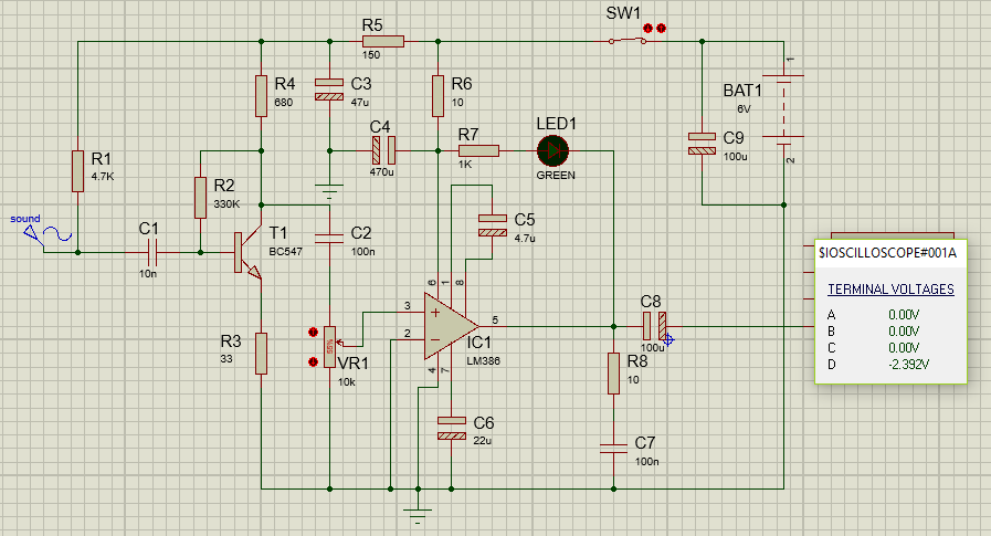
The simulation of Listening bug circuit is shown in figure 2. Instead of microphone we are using sine wave at the input. Cathode of LED is connected to output of IC (pin 5) as shown in figure 2. The LED start to blink only when microphone detect the sound. As the output of this circuit is sine wave in nature. When the wave is of positive cycle the cathode of LED is at same potential or in higher potential then cathode as a result LED doesn’t glow. But when the wave is of negative cycle the LED start to glow because it get lower potential at cathode then anode. As you can see in figure below LED is glowing because it get lower potential (-2.392V at channel D of oscilloscope).

PARTS LIST OF LISTENING BUGS USING OP-AMP LM386
| Resistor (all ¼-watt, ± 5% Carbon) |
| R1 = 4.7 KΩ
R2 = 330 KΩ R3 = 33 Ω R4 = 640 Ω R5 = 150 Ω R6 = 10 Ω, 0.5W R7 = 1 KΩ R8 = 10 Ω VR1 = 10 KΩ (LIN. POT.) |
| Capacitors |
| C1 = 10 nF (Ceramic Disc)
C2, C7 = 100 nF (Ceramic Disc) C3 = 47 µF/16V (Electrolytic Capacitor) C4 = 470 µF/16V (Electrolytic Capacitor) C5 = 4.7 µF/16V (Electrolytic Capacitor) C6 = 22 µF/16V (Electrolytic Capacitor) C8 = 100 µF/16V (Electrolytic Capacitor) C9 = 1000 µF/16V (Electrolytic Capacitor) |
| Semiconductors |
| IC1 = LM386 (op-amp)
T1 = BC547 (General purpose NPN transistor) |
| Miscellaneous |
| MIC1 = Condenser Microphone
SW1 = ON/OFF switch BAT1 = 6V battery (4*1.2V) Earphone |
