Instrumentation Amplifier | Derivation | Advantage

This article is all about instrumentation amplifier, its derivation, configuration, advantage and disadvantage. We had also try to describe different types of instrumentation amplifier like single op-amp based instrumentation amplifier, instrumentation amplifier using two and three op-amp.

The electrical transducer low level output signal often require to be amplified before further processing and this task is usually get accomplish by use of instrumentation amplifier.

There are several important characteristics of an instrumentation amplifier that set it apart from operational amplifier.

  1. Instrumentation amplifier have finite gain which is selectable within precise value of range with high gain accuracy and gain linearity.
  2. The instrumentation amplifier has a high impedance differential input.
  3. The instrumentation amplifier has high common mode rejection ratio (CMMR) and a high common mode voltage range.
  4. Instrumentation amplifier has high stability of gain with low temperature coefficient.

These listed out characteristics make an instrumentation amplifier superior to most OP-AMP.

Instrumentation Amplifier (IA) using one Op-amp

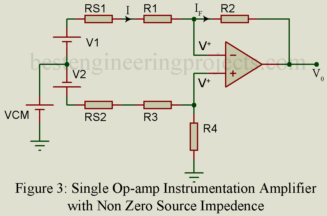
Vcm is external noise (common mode signal) and assuming internal resistance of source V1 and V2 are negligible and also assuming op-amp to be ideal.

instrumentation amplifier using one op-amp

V^+ = \dfrac{R_4}{R_3 + R_4}(V_2 + V_{cm})        …..(1)

Current through resistor R1 = current through resistor R2

\dfrac{V_{cm}+V_1-V^+}{R_1} = \dfrac{V^+-V_0}{R_2}       …..(2)

Combining equation (1) and (2) and eliminating V+, we get,

V_0 = V{cm}\dfrac{R_4\times R_1-R_2\times R_3}{R_1\times (R_3 + R_4)}-\dfrac{R_2}{R_1}V_1 + \dfrac{R_4}{R_3}(\dfrac{1+\dfrac{R_2}{R_1}}{1+\dfrac{R_4}{R_3}})V_3     …..(3)

Instrumental Amplifier shall reject common mode signal i.e. V0 shall be independent of Vcm.

i.e. V_{cm}\dfrac{R_4\times R_1-R_2\times R_3}{R_1\times (R_3 + R_4)} = 0

R_4\times R_1-R_2\times R_3=0 \dfrac{R_2}{R_1} = \dfrac{R_4}{R_3}

The expression of output voltage from equation 3.

V_0 = \dfrac{R_2}{R_1}(V_2-V_1)

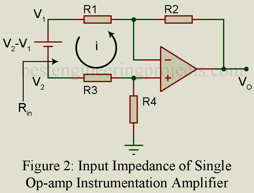
Input Impedance of single op-amp instrumental Amplifier

\dfrac{R_4}{R_3} = \dfrac{R_2}{R_1} for common mode signal rejection.

R_{in} = \dfrac{V_2-V_1}{i} (V_2-V_1) = i\times R_3 + i\times R_1 \dfrac{V_2-V_1}{i} = R_1 + R_3 R_{in} = R_1 + R_3

(For R1 = R3 and R4 = R2 then Rin = 2R1)

input impedance of single op-amp instrumentation amplifier

Limitation of Single Op-Amp Instrumental Amplifier

Difficult to change gain because \dfrac{R_2}{R_1} = \dfrac{R_4}{R_3} shall be maintain at the same time. and for large gain R1 shall be kept relatively small which means input impedance decreases causing source overloading.

Single Op-amp  Instrumental Amplifier with non-zero source impedance

V^+ = \dfrac{R_4}{R_3+R_{s2}+R_4}\times (V_2+V_{cm})          ……(4)

I = I_f

\dfrac{V_{cm}+V_1-V^+}{R_1+R_{s1}} = \dfrac{V^+-V_0}{R_2}        ……(5)

instrumentation amplifier with non zero source impedance

From equation 4 and 5, eliminating V+

V_0 = (\dfrac{R_4}{R_{12}+R_3+R_4}-\dfrac{R_2}{R_{s1}+R_1}+\dfrac{R_2}{R_{s1}+R_1}-\dfrac{R_4}{R_{s1}+R_3+R_4})V_{CM}+\dfrac{R_4}{R_{s2}+R_3+R_4}\times(1+\dfrac{R_2}{R_{s1}+R_1})V_2-\dfrac{R_2}{R_{s1}R_1}V_1       …..(6)

For complete rejection of common mode signal, Vcm containing term shall be zero.

\dfrac{R_4}{R_{s2}+R_3+R_4}-\dfrac{R_2}{R_{s1}+R_1}+\dfrac{R_2}{R_{s1}+R_1}\times \dfrac{R_4}{R_{s2}+R_3+R_4} = 0 \dfrac{R_1+R_{s1}}{R_2} = \dfrac{R_3+R_{s2}}{R_4} \dfrac{R_2}{R_1+R_{s1}} = \dfrac{R_4}{R_3+R_{s2}}

From equation (3) V_0 = \dfrac{R_2}{R_1+R_{s1}}\times (V_2-V_1)

If source impedance are unequal common mode rejection is degraded.

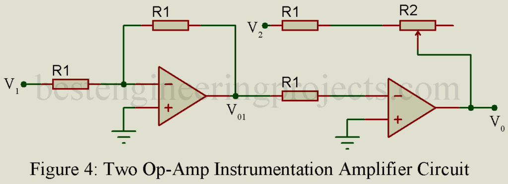
Two Op-Amp Instrumental Amplifier

V_{01} = \dfrac{-R_1}{R_1}\times V_1 = -V_1 V_0 = \dfrac{-R_2}{R_1}\times V_2 \dfrac{-R_2}{R_1}\times V_{01} V_0 = \dfrac{-R_2}{R_1}\times (V_2-V_1)

two op-amp instrumentation amplifier

  • Gain can be adjusted by adjusting variable resistor R2
  • For good CMRR (Common mode rejection ratio) four resistors shall be matched.
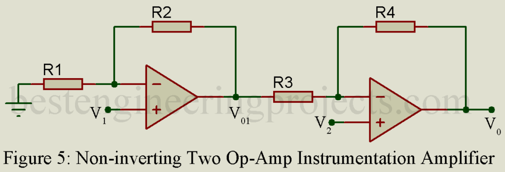
  • For high input impedance input shall be given in non-inverting terminal.


V_{01} = (1+\dfrac{R_2}{R_1})\times V_1 V_0 = (1 + \dfrac{R_4}{R_3})\times V_2-\dfrac{R_4}{R_3}\times V_{01} V_0 = (1+\dfrac{R_4}{R_3})\times V_2-\dfrac{R_4}{R_3}\times (1+\dfrac{R_2}{R_1})\times V_1

If \dfrac{R_4}{R_3} = \dfrac{R_2}{R_1}

V_0 = (! + \dfrac{R_2}{R_1})\times (V_2-\dfrac{R_2}{R_1}\times V_1)

non-inverting two op-amp instrumentation amplifier

  • It has a high input impedance.

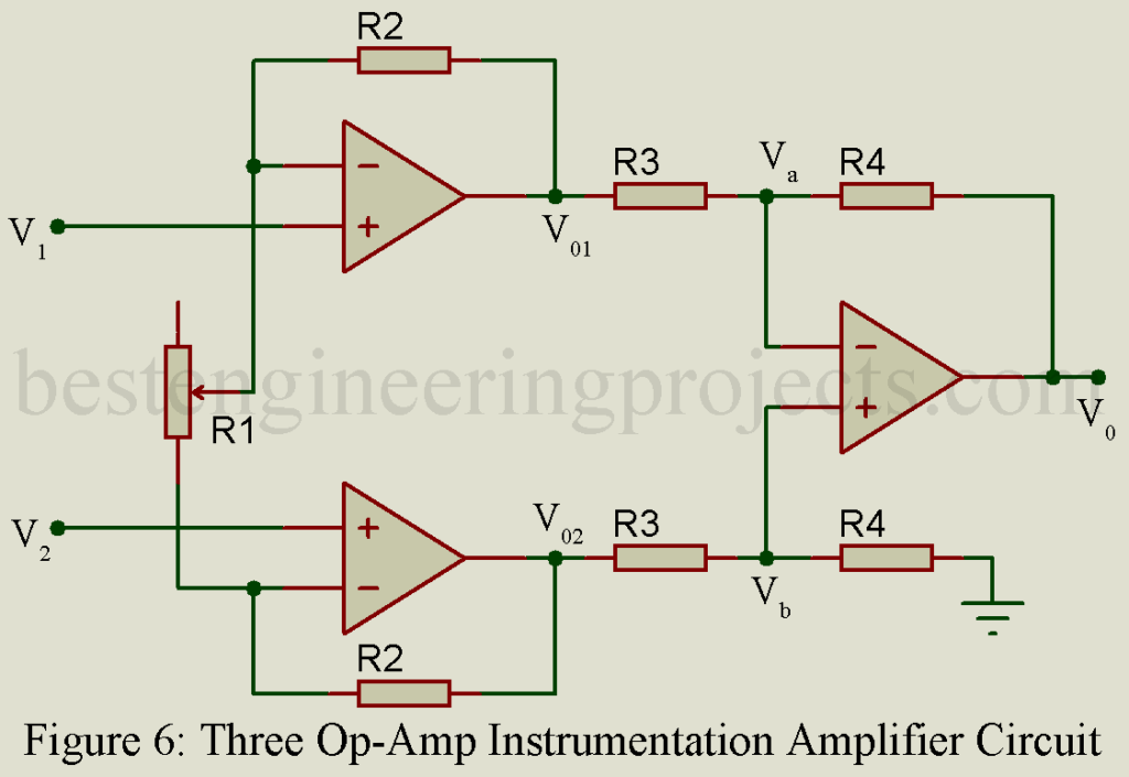
Three Op-amp Instrumental amplifier

In this circuit three OP-Amp are used and a potentiometer is provided to permit adjusting the scale factor of circuit, then from above diagram we can write

\dfrac{V_{01}-V_1}{R_2} = \dfrac{V_1-V_2}{R_1}       …..(7)

Or, \dfrac{V_{01}}{R_2} = \dfrac{V_1}{R_1}+\dfrac{V_1}{R_2}-\dfrac{V_2}{R_1}

Or, V_{01} = \dfrac{R_2}{R_1}\times V_1 + V_1-\dfrac{R_2}{R_1}\times V_2

Or, V_{01} = V_1 + \dfrac{R_2}{R_1}\times [V_1-V_2]        …..(8)

Similarly,

\dfrac{V_2-V_{02}}{R_2} = \dfrac{V_1-V_2}{R_1} -\dfrac{V_{02}}{R_2} = \dfrac{V_1}{R_1}-\dfrac{V_2}{R_2}-\dfrac{V_2}{R_1} \dfrac{V_{02}}{R_2} = \dfrac{V_2}{R_2} + \dfrac{V_2}{R_1}-\dfrac{V_1}{R_1} V_{02} = V_2 + \dfrac{R_2}{R_1}\times V_2-\dfrac{R_2}{R_1}\times V_1

V_{02} = V_2 + \dfrac{R_2}{R_1}\times [V_2-V_1]          ……(9)

three op-amp instrumentation amplifier

Now, for equation 2 and 4,

V_{01}-V_{02} = V_1 + \dfrac{R_2}{R_1}\times [V_1-V_2]-V_2-\dfrac{R_2}{R_1}\times [V_2-V_1] = V_1-V_2+\dfrac{R_2}{R_1}\times V_1-\dfrac{R_2}{R_1}\times V_2-\dfrac{R_2}{R_1}\times V_2 + \dfrac{R_2}{R_1}\times V_1 V_1-V_2+2\times \dfrac{R_2}{R_1}\times V_1-2\times \dfrac{R_2}{R_1}\times V_2 V_1-V_2 + 2\times \dfrac{R_2}{R_1}\times [V_1-V_2]

V_{01}-V_{02} = (V_1-V_2)\times [1 + 2\times \dfrac{R_2}{R_1}]           ………(10)

Now applying KCL at node Va, one can write

\dfrac{V_a-V_{01}}{R_3}+\dfrac{V_a-V_o}{R_4} = 0 \dfrac{V_a}{R_3}+\dfrac{V_a}{R_4}-\dfrac{V_{01}}{R_3}-\dfrac{V_0}{R_4} = 0 \dfrac{V_0}{R_4} = \dfrac{V_a}{R_3}+\dfrac{V_a}{R_4}-\dfrac{V_{01}}{R_3} \dfrac{V_a}{R_3}+\dfrac{V_a}{R_4} = \dfrac{V_0}{R_4}+ \dfrac{V_{01}}{R_3} V_a\times (\dfrac{R_3+R_4}{R_3R_4}) = \dfrac{V_0}{R_4}+\dfrac{V_{01}}{R_3}

V_a = [\dfrac{R-3}{R_3+R_4}\times V_0 + \dfrac{R_4}{R_3+R_4}\times V_{01}]         ……(11)

Similarly, applying kcl at node Vb,

\dfrac{V_b-V_{02}}{R_3}+\dfrac{V_b}{R_4} = \dfrac{V_b}{R_3} + \dfrac{V_b}{R_4}-\dfrac{V_{02}}{R_3} = 0 V_b\times (\dfrac{R_3+R_4}{R_3R_4}) = \dfrac{V_{02}}{R_3}

V_b = \dfrac{R_4}{R_3 + R_4}\times V_{02}          ……(12)

For perfect balance, Va must be equal to Vb. Thus, one can write as

Va = Vb

\dfrac{R_3}{R_3+R_4}\times V_0 + \dfrac{R_4}{R_3 + R_4}\times V_{01} = \dfrac{R_4}{R_3+R_4} \times V_{02} \dfrac{R_3}{R_3+R_4}\times V_0 = \dfrac{R_4}{R_3+R_4}\times V_{02}-\dfrac{R_4}{R_3+R_4}\times V_{01} \dfrac{R_3}{R_3+R_4}\times V_0 = \dfrac{R_4}{R_3+R_4} \times [V_{02}-V_{01}] V_0 = \dfrac{R_4}{R_3}\times [V_{02}-V_{01}]

V_0 = -\dfrac{R_4}{R_3}\times [V_{01}-V_{02}]          …….(13)

From equation 12 and 13 we can write

V_0 = -\dfrac{R_4}{R_3}\times [V_1-V_2]\times [1+ 2\times \dfrac{R_2}{R_1}]

V_0 = \dfrac{R_4}{R_3}\times [V_2-V_1]\times [1 + 2\times \dfrac{R_2}{R_1}]         ……(14)

This gain can be expressed as

A_v = \dfrac{V_0}{(V_2-V_1)}

A_v = \dfrac{R_4}{R_3}[1+ 2\times \dfrac{R_2}{R_1}]        …..(15)

The equation 14 yields an output and that equation 15, provides gain of an instrumentation amplifier.

3 Op-amp Instrumentation amplifier has two stages in which 1st stage provides high input impedance (ideally infinity) because both input are at non-inverting terminals. Second stage completely rejects common mode signal i.e. high CMRR, because \dfrac{R_4}{R_3} = \dfrac{R_4}{R_3}. Gain can be verified by changing variable resistor R2.

Leave a Comment