Here in this article, you will learn about the RTC module and how to interface this module with Arduino and ESP boards like Arduino MEGA, Arduino UNO, Arduino NANO, ESP32, Node MCU, and Arduino NANO.
How to interface RTC module with Arduino and ESP Board
RTC acronymic for Real-Time Clock is an electronic Integrated Circuit (IC) that keeps track of time around the clock. It is more like a computer clock where once we set it up gives us accurate time even after the power outage. Before we delve into the interfacing of RTC with ESP32 and another microcontroller, how about we check some facts about RTC? But wait, what is ESP32? ESP32 is a microcontroller chip with Wi-Fi and a dual-mode Bluetooth system integrated into it. It is used in IoT devices, electronics, and of course mobile phones.
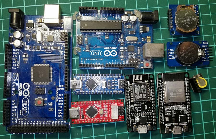 Figure 1: RTC with Different Development Board
How does RTC keep track of time?
RTC module contains a crystal oscillator of 32.768KHz (generally). This is the same frequency used in digital and quartz clocks. In a second, it oscillates about 211 = 32,768 Hz and uses an updated binary counter to track time. Initially, RTC doesn’t know the correct time thus at first, we have to set a current time. This time is saved in RTC’s internal memory which updates over time with no or negligible error.
Does RTC need an uninterrupted power supply?
Every electronic device requires an uninterrupted power supply. RTC, being a computer clock, an electronic device, is not an exception either. So, Yes – to keep tracking the current time and keep updating accordingly, RTC requires an uninterrupted power supply. And hence, it becomes obvious that with a power outage, there is no update of the current time. Thus, it has a battery backup for continuous timekeeping. It requires very low power (continuous less than 1uW) thus interruption of primary power supply doesn’t affect current time because of the in-built lithium battery.
Why do we need RTC?
Almost all microcontrollers have internal timers; they do have oscillators but we still need RTC for time-keeping functions. Like, we would want to keep track of every second, every minute, hour or day, month, year so on and so forth, wouldn’t we? Let’s validate what we just came to know. Let’s look at an example below.
AVR microcontrollers (Arduino) have a built-in timekeeper function called millis() function. By using this function one can track second, minute, hour, day, or even a month. This millis() function needs a continuous power supply to keep tracking time and it sets to zero when the power supply is interrupted i.e. whenever an Arduino or a microcontroller resets (either due to failure of power supply or using reset switch) millis() function starts to count from zero millisecond.
Even if we maintain a continuous power supply to the microcontroller, its timekeeper resets after a fixed time interval. The millis() function is of an unsigned long type variable. The unsigned long variable is of 4 bytes or we can say 32-bits. The maximum value that millis can hold is
232 = 4294967296 milliseconds
i.e. 49 days and 17 hours.
When the millis function increases by a millisecond from 4,294,967,296, it rolls over to zero!
These are the reasons for using RTC instead of microcontroller internal timekeeping.
How to calculate the accuracy of RTC?
Generally, the accuracy of crystal RTC is about  to
to  per million. Let’s convert this to second:

i.e. there is the deviation of 1 second in every 10000 seconds which is equal to 8.6 seconds per day.
Similarly,

i.e. there is the deviation of 1 second in every 50000 seconds which is equal to 1.7 seconds per day.
So, the accuracy of general-purpose crystal RTC is between 1.7seconds to 8.6 seconds.
The value of accuracy differs or we can also say that it is low for temperature-compensated crystal oscillator RTC (DSB3231).
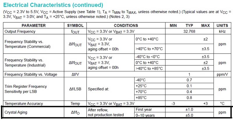
Figure 2: DS3231 Datasheet showing Crystal Aging
According to its datasheet for the first year, its accuracy is about  ppm i.e. there’s a deviation of 1 second in every 1 million seconds. If we calculate this time in the day, then for the first year there might be a deviation of 1 second in every 11.57 days. This is quite good and the error in time is negligible but this accuracy is not the same for a lifetime due to the crystal aging effect. After the 1st year, its accuracy decreases to
  ppm i.e. 1 second in every 200000 seconds i.e. there would be a deviation of 1 second in every 2.32 days. Even after a year there would be a minor deviation of about 2.62 minutes and is considered negligible.
To overcome this error, one can synchronize RTC with NTP (Network Time Protocol).
Check out the article Arduino NTP Clock using Arduino: Arduino NTP Clock using NodeMCU and DS3231
Circuit Description How to interface RTC module with Arduino and ESP Board
Figure 1 shows the circuit, built around ESP32, RTC Module DS3231, and I2C LCD. The connection of this component is very simple and straightforward. RTC module and LCD share common I2C pins (GPIO 21 and GPIO 22).
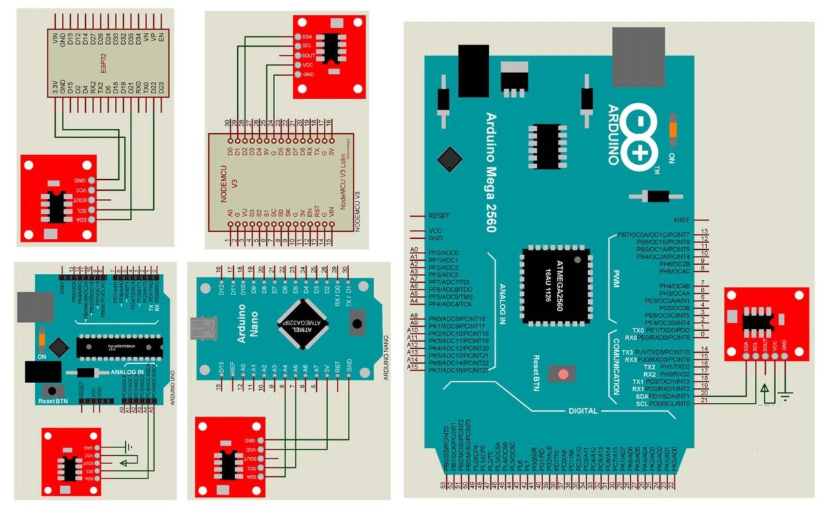
Figure 3: Circuit Diagram of How to interface RTC with Arduino and ESP Board
Power Supply: Vin pin of ESP32, Vcc pin of LCD and DS3231 is sorted together and connected to +5V supply and ground of all these components is connected to ground pin of LCD.
Note: LCD requires +5V to operate where DS3231 can work with 3.3V also.
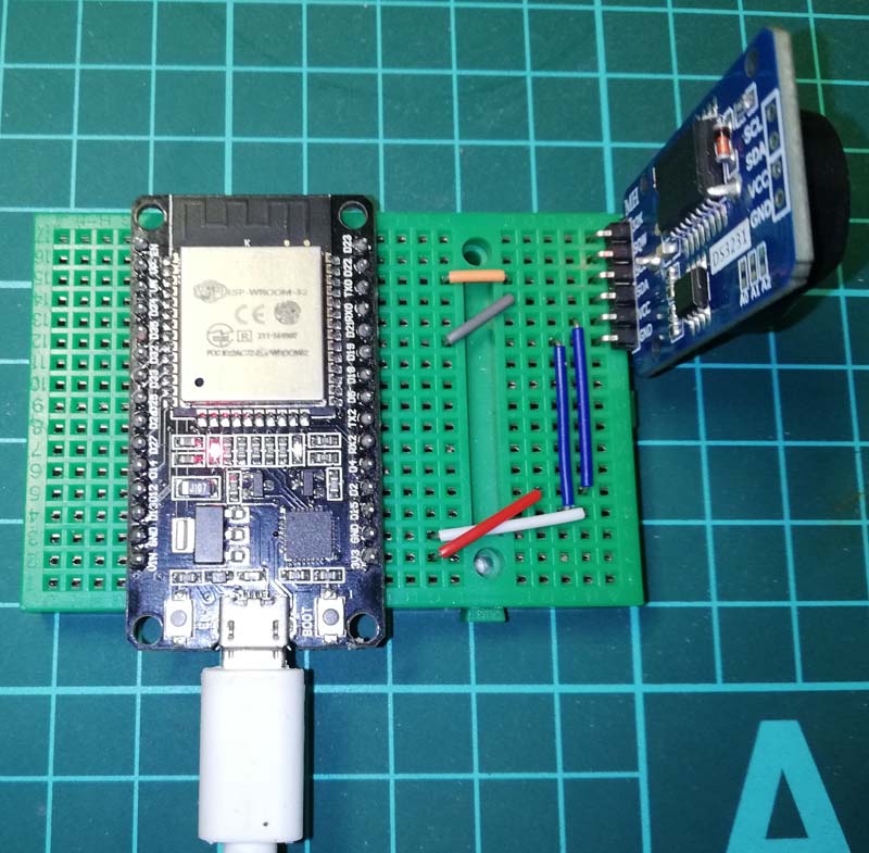 Figure 4: Author Prototype of How to Interface RTC with ESP32
Software Code:
Software code is written in Arduino programming language (based on C/C++), before uploading code change the current date, remove the comment and upload it. After uploading, add the comment to this time setup line and re-upload it.
|
1 2 |
// DS3231 seconds, minutes, hours, day, date, month, year setDS3231time(00,07,22,4,29,7,20); |
Software Code:
|
1 2 3 4 5 6 7 8 9 10 11 12 13 14 15 16 17 18 19 20 21 22 23 24 25 26 27 28 29 30 31 32 33 34 35 36 37 38 39 40 41 42 43 44 45 46 47 48 49 50 51 52 53 54 55 56 57 58 59 60 61 62 63 64 65 66 67 68 69 70 71 72 73 74 75 76 77 78 79 80 81 82 83 84 85 86 87 88 89 90 91 92 93 94 95 96 97 98 99 100 101 102 103 104 105 106 107 108 109 110 111 112 113 114 115 116 117 |
// Software code for interfacing RTC with different development board #include "Wire.h" #define DS3231_I2C_ADDRESS 0x68 // Convert normal decimal numbers to binary coded decimal byte decToBcd(byte val) { return( (val/10*16) + (val%10) ); } // Convert binary coded decimal to normal decimal numbers byte bcdToDec(byte val) { return( (val/16*10) + (val%16) ); } void setup() { Serial.begin(9600);; Wire.begin(); // set the initial time here: // DS3231 seconds, minutes, hours, day, date, month, year //setDS3231time(00,07,22,4,29,7,20); } void setDS3231time(byte second, byte minute, byte hour, byte dayOfWeek, byte dayOfMonth, byte month, byte year) { // sets time and date data to DS3231 Wire.beginTransmission(DS3231_I2C_ADDRESS); Wire.write(0); // set next input to start at the seconds register Wire.write(decToBcd(second)); // set seconds Wire.write(decToBcd(minute)); // set minutes Wire.write(decToBcd(hour)); // set hours Wire.write(decToBcd(dayOfWeek)); // set day of week (1=Sunday, 7=Saturday) Wire.write(decToBcd(dayOfMonth)); // set date (1 to 31) Wire.write(decToBcd(month)); // set month Wire.write(decToBcd(year)); // set year (0 to 99) Wire.endTransmission(); } void readDS3231time(byte *second, byte *minute, byte *hour, byte *dayOfWeek, byte *dayOfMonth, byte *month, byte *year) { Wire.beginTransmission(DS3231_I2C_ADDRESS); Wire.write(0); // set DS3231 register pointer to 00h Wire.endTransmission(); Wire.requestFrom(DS3231_I2C_ADDRESS, 7); // request seven bytes of data from DS3231 starting from register 00h *second = bcdToDec(Wire.read() & 0x7f); *minute = bcdToDec(Wire.read()); *hour = bcdToDec(Wire.read() & 0x3f); *dayOfWeek = bcdToDec(Wire.read()); *dayOfMonth = bcdToDec(Wire.read()); *month = bcdToDec(Wire.read()); *year = bcdToDec(Wire.read()); } void displayTime() { byte second, minute, hour, dayOfWeek, dayOfMonth, month, year; // retrieve data from DS3231 readDS3231time(&second, &minute, &hour, &dayOfWeek, &dayOfMonth, &month, &year); // send it to the serial monitor Serial.print(hour, DEC); // convert the byte variable to a decimal number when displayed Serial.print(":"); if (minute<10) { Serial.print("0"); } Serial.print(minute, DEC); Serial.print(":"); if (second<10) { Serial.print("0"); } Serial.print(second, DEC); Serial.print(" "); Serial.print(dayOfMonth, DEC); Serial.print("/"); Serial.print(month, DEC); Serial.print("/"); Serial.print(year, DEC); Serial.print(" Day of week: "); switch(dayOfWeek){ case 1: Serial.println("Sunday"); break; case 2: Serial.println("Monday"); break; case 3: Serial.println("Tuesday"); break; case 4: Serial.println("Wednesday"); break; case 5: Serial.println("Thursday"); break; case 6: Serial.println("Friday"); break; case 7: Serial.println("Saturday"); break; } } void loop() { displayTime(); // display the real-time clock data on the Serial Monitor, delay(1000); // every second } |