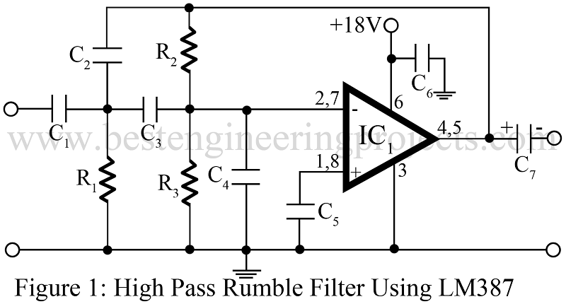
An electric filter or simply a filter is an electric network that passes or allows without loss, the transmission of electric signal within a certain frequency range but stops or disallows transmission of electric signal outside this frequency range.
The three most-popular filters found in audio equipment are the High Pass Filter (rumble filter), Low pass filter (scratch filter), and speech filters. The rumble filter is a high-pass filter, used to suppress the low-frequency rumbling sound associated with old and worn-out turntable and tape deck mechanisms. Here we explain to you how a high pass filter or rumble filter works with a circuit diagram and description.
We also define a high pass filter or rumble filter circuit as it passes all frequencies above a specified frequency, called the cutoff frequency fc, and rejects all frequencies below fc.
Circuit description of High pass filter or Rumble filter using LM387
The circuit of the high pass filter is built around general-purpose op-amp IC LM387. Input from the amplifier is given to the inverting input pin 2 and pin 7 through coupling capacitors C1 and C3. Unwanted frequency is filtered by capacitor C4. Where capacitor C2 is used as a feedback capacitor connected from output to input. Output is taken from pin 4 and pin 5 through capacitor C7. Non-inverting pin 1 and 8 is connected to the ground through capacitor C5.
F0 = 60Hz,
Butter worth Q = 0.707
A0 = 1
SLOPE = -12dB (OCTAVE)
The working of the circuit high pass filter using LM348/LM741 is the same as circuit 1 (High pass rumble filter using LM387). Capacitor C4 is only connected when IC lM348 is used not while using LM741.
PARTS LIST OF HIGH PASS FILTER USING LM387 (CIRCUIT 1)
| Resistor (all ¼-watt, ± 5% Carbon) |
| R1 = 220 KΩ
R2 = 1 MΩ R3 = 180 KΩ |
| Capacitors |
| C1 – C3 = 5.6 kPF (Ceramic Disc)
C4 = 0.033 µF (Ceramic Disc) C5, C6 = 0.1 µF (Ceramic Disc) C7 = 10 µF/12V (Electrolytic Capacitor) |
| Semiconductors |
| IC1 = LM387 (Operational Amplifier) |
PARTS LIST OF HIGH PASS FILTER USING LM741/LM348 (CIRCUIT 2)
| Resistor (all ¼-watt, ± 5% Carbon) |
| R1 = 220 KΩ
R2 = 1 MΩ |
| Capacitors |
| C1 – C3 = 5.6 kPF (Ceramic Disc)
C4 = 0.047 µF (Ceramic Disc) C5, C6 = 0.1 µF (Ceramic Disc) |
| Semiconductors |
| IC1 = LM348/LM741 (Operational Amplifier) |


Good explanation of the high pass filter and everything you can do with it. Thanks so much for the great information.