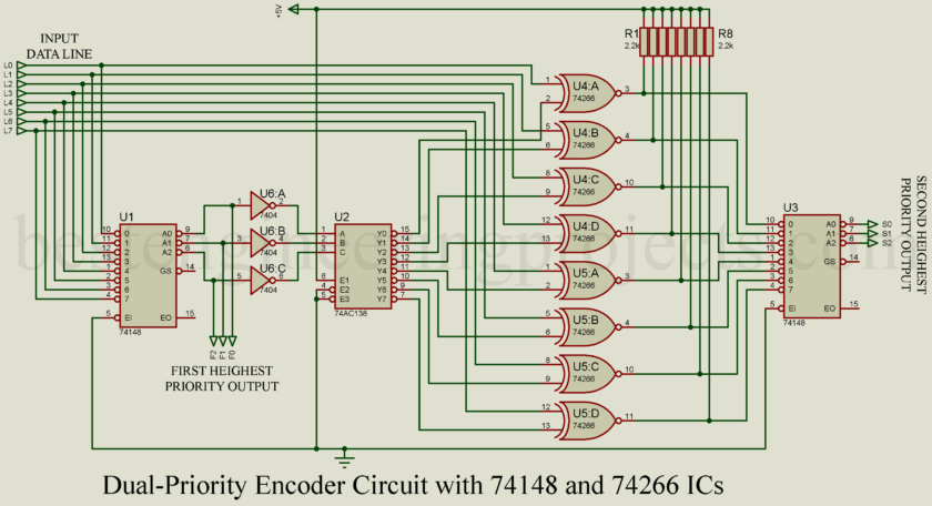
Imagine this: you’re a traffic cop in the middle of a very busy intersection. Cars from every direction are honking, each one demanding to go first. You’ve gotta make a decision, right? Now, picture that some of these cars have more “urgency” than others—maybe an ambulance is in the mix, but there’s also a VIP car behind it. Wouldn’t it be useful to know not only who needs to go first but also who should go second? Well, in the world of digital electronics, that’s what we’re doing with this dual-priority encoder circuit—finding not just the “most important” signal but also the “second-most important” one.
Now, you might be thinking, “Isn’t a priority encoder enough?” Sure, a basic priority encoder like the 74148 IC does the job if you just want the top-priority signal. But sometimes, you need more. Sometimes you need to know, “If my top-priority line is busy, what’s next?” That’s where our dual-priority encoder circuit comes in, and it’s not as complicated as it sounds.
Components You’ll Need
For this project, you need a few key digital ICs. First, we have two 74148 ICs. These are the brains of the operation that decide which signal is of the highest priority. Next, we have a 74AC138 decoder to help us translate those priorities into action. Finally, we have 74266 XNOR gates. They are like bouncers in a club, canceling out the highest priority line so that we may find who is next in line. A few resistors to make things stable, and don’t forget every good circuit needs some ‘grounding‘.
How Does This Circuit Work? Let’s Dive In
First things first, let’s figure out the “top priority.”
The 74148 IC (let’s call it U1) is like your main priority detector. It checks out each input line—L0 through L7—and spits out a 3-bit binary code that represents which line has the highest priority. This code, which we’ll call F2,F1,F0F_2, F_1, F_0F2,F1,F0, tells us the number of the highest-priority line.
But wait! It’s in active-low format, which means the output is inverted. A little confusing, right? So we use three NOT gates to flip it back to what we need. Now, we know who’s on top.
The Decoder Steps In
Once we’ve got our highest-priority line identified, we pass this info to the 74AC138 decoder (U2 in the diagram). It’s like a signal translator, converting the 3-bit binary output from U1 into a specific output line that goes low. Let’s call this line MpM_pMp, where ppp represents the highest-priority input line. All other lines stay high, making it easy for us to zero in on the top dog.
Think of it this way: If L6 is our highest-priority line, then M6M_6M6 goes low, while everything else stays high.
“Canceling” the Top Priority with XOR Gates
At this point, we know the most important signal. But we don’t just want the top priority, remember? We want the second-highest too. This is where things get a little clever.
We use XNOR gates (74266) to cancel out the highest-priority line. Each data line (L) pairs up with a corresponding decoded line (M), and together they pass through an XNOR gate. When both L and M are low, the output from that gate goes high, effectively “removing” the top-priority line from the equation.
So, if L6 is our top priority, then after it passes through the XNOR gate, it’s no longer considered, leaving us with a new set of inputs where L6 is effectively canceled. All that’s left now is to find the highest-priority line among the remaining inputs.
Finding the Second-Highest Priority with the Second Encoder
We feed these modified outputs (let’s call them U4:A through U5:D) into the second 74148 IC (U3). This one works just like U1, scanning the inputs and finding the highest priority—but this time, it’s finding the “highest” among what’s left. So, we’re left with the second-highest priority in the original data lines.
If L6 was the highest, and L3 was the next one down, then U3 would encode L3 as the second-highest priority and output it as S2,S1,S0.
An Example to Tie It All Together
Let’s say the input lines (L0 through L7) look like this: X X X 0 1 1 0 1.
- U1 detects the highest-priority line, L6, and outputs 0 0 1.
- U2 decodes this and sets M6 to 0, marking L6 as the top priority.
- The XNOR gates cancel out L6, so the modified lines become X X X 0 1 1 1 1.
- Now U3 sees that L3 is the highest priority among the new set and outputs 1 0 0, which tells us L3 is next in line.
So, in the end, we’ve got both the highest (L6) and second-highest (L3) priorities. Neat, right?
Why Bother with Dual-Priority?
So why all this fuss? In a single-word answer: Efficiency. Imagine you’re managing multiple interrupts in a microcontroller. With a single priority encoder, you might miss out on knowing what’s next in line, which could slow things down if there’s a delay handling the first signal. By capturing both levels of priority, you’re ready to move on as soon as the top-priority task is done.
Wrapping Up
This dual-priority encoder circuit is a fantastic tool for any digital electronics project where signal prioritization matters. By layering priority levels, you get a snapshot of both the most important and second-most important signals in an instant.
Projects like these are why digital electronics are so exciting. With just a few ICs—74148, 74AC138, and 74266—you’re able to build a system that brings efficiency to signal management, making it an essential piece for automation, data multiplexing, and more.
So go ahead, try building this circuit, and see how it can add value to your next digital electronics project. It might just be the missing piece you didn’t know you needed.
