Digital Signal Encoding Formats: Transmission of digital data using a binary format (+5 V-hi, 0.0 V-low) is usually limited to short distances such as a computer to a printer interface. Typically the binary data are transmitted serially over a single wire, fiber, or RF link. This requires that the binary data be encoded in such a way that highs and lows can easily be detected. The transmission systems typically use a serial transmission system that is either asynchronous or synchronous. This requires the addition of clocking information in the data for synchronous systems.
The digital signal encoding formats presented in this section are the most commonly used PCM waveforms. (Note that we are identifying the encoding format as a pulse-code-modulated waveform.) The waveforms are classified into one of four encoding groups:
Classification of Digital Signal Encoding Formats
- NRZ-nonreturn-to-zero
- RZ-return-to-zero
- Phase-encoded and delay modulation
- Multilevel binary
The encoding formats described are of the baseband type. A baseband signal is not modulated. These waveforms are still in a binary or pseudo-binary format, so therefore they are classified as baseband.
The NRZ Group | Digital Signal Encoding Formats
The NRZ group is a popular method for encoding binary data. NRZ codes are also one of the easiest to implement. NRZ codes get their name from the fact that the data signal does not return to zero during an interval. In other words, NRZ codes remain constant during an interval. Because of this, the code has a dc component in the waveform. For example, a data stream containing a chain of l’s or 0’s will appear as a de signal at the receive side. Look at the waveform for the NRZ-L code that is shown in Fig. 1. Notice that the code remains constant for several clock cycles for a series of zeros or ones.
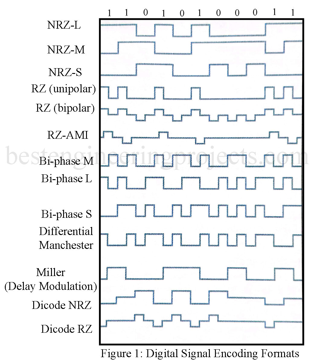
Another important factor to consider is that the NRZ codes do not contain any self. synchronizing capability. NRZ codes will require the use of start bits or some kind of synchronizing data pattern to keep the transmitted binary data synchronized. There are three coding schemes in the NRZ group, NRZ-L (level), NRZ-M (mark), and NRZ-S (space). The waveforms for these formats are provided in Fig. 1. The NRZ code descriptions are provided in Table 1.
| TABLE 1 NRZ Codes |
| NRZ-L (Nonreturn to zero-level)
1 (Hi)-high level 0 (Low)-low level |
| NRZ-M (Nonreturn to zero-mark)
1 (Hi)-transition at the beginning of the interval 0 (Low)—no transition |
| NRZ-S (Nonreturn to zero-space)
1 (Hi)-no transition 0 (Low)-transition at the beginning of the interval |
The RZ Codes
The RZ-unipolar code shown in Fig. 1 has the same limitations and disadvantages as the NRZ group. A dc level appears on the data stream for a series of l’s or 0’s. Synchronizing capabilities are also limited. These deficiencies are overcome by modifications in the coding scheme, which include using bipolar signals and alternating pulses. The RZ-bipolar code provides a transition at each clock cycle, and a bipolar pulse technique is used to minimize the dc component. Another RZ code is RZ-AMI. The alternate-mark-inversion code provides alternating pulses for the l’s. This technique virtually removes the dc component from the data stream, but since a data value of 0 is 0 V the system can have poor synchronizing capabilities if a series of 0’s is transmitted. This deficiency can also be overcome by the transmission of the appropriate start, synchronizing, and stop bits. Table 2 provides descriptions of the RZ codes.
| TABLE 2 RZ Codes |
| RZ (unipolar) (Return-to-zero)
1 (Hi)-transition at the beginning of the interval 0 (Low)-no transition |
| RZ (bipolar) (Return-to-zero)
1 (Hi)-positive transition in the first half of the clock interval 0 (Low)-negative transition in the first half of the clock interval |
| RZ-AMI (Return-to-zero-alternate-mark inversion)
1 (Hi)-transition within the clock interval alternating in direction 0 (Low)-no transition |
Bi-phase and Miller Codes
The popular names for phase-encoded and delay-modulated codes are bi-phase and Miller codes. Bi-phase codes are very popular for use in optical systems, satellite telemetry links, and magnetic recording systems. Bi-phase M is used for encoding SMPTE (Society of Motion Picture and Television Engineers) time-code data for recording on videotapes. The bi-phase code is an excellent choice for this type of media because the code does not have a dc component to it. Another important benefit of the code is self-synchronizing, or self-clocking. This feature allows the data stream speed to vary (tape shuttle in fast and slow search modes) while still providing the receiver with clocking information.
The bi-phase L code is commonly known as Manchester Coding. This code is used on the Ethernet standard IEEE 802.3 for local area networks (LAN). Figure 1 provides examples of these codes and Table 3 summarizes their characteristics.
| Table 3 Phase-Encoded and Delay-Modulation (Miller) Codes |
| Bi-phase M (Bi-phase-mark)
1 (Hi)-transition in the middle of the clock interval 0 (Low)-no transition in the middle of the clock interval Note: There is always a transition at the beginning of the clock interval. |
| Bi-phase L (Bi-phase-level / manchester)
1 (Hi)-transition from high to low in the middle of the clock interval 0 (Low)-transition from low to high in the middle of the clock interval |
| Bi-phase S (Bi-phase-space)
1 (Hi)-no transition in the middle of the clock interval 0 (Low)-transition in the middle of the clock interval Note: There is always a transition at the beginning of the clock interval. |
| Differential Manchester
1 (Hi)-transition in the middle of the clock interval 0 (Low)-transition at the beginning of the clock interval |
| Miller/delay modulation
1 (Hi)-transition in the middle of the clock interval 0 (Low)-no transition at the end of the clock interval unless followed by a zero |
Multilevel Binary Codes
Codes that have more than two levels representing the data are called Multilevel binary codes. In many cases, the codes will have three levels. We have already examined two of these codes in the RZ group, RZ (bipolar) and RZ-AMI. Also included in this group are Dicode NRZ and Dicode RZ. Table 4 summarizes the multilevel binary codes.
| Table 4 Multilevel Binary Codes |
| Dicode NRZ
One-to-zero and zero-to-one data transitions change the signal polarity. If the data remain constant, then a zero-level is output. |
| Dicode RZ
One-to-zero and zero-to-one data transitions change the signal polarity in half-step voltage increments. If the data don’t change, then a zero-voltage level is output. |
hello
what are the Fiber optic network coding techniques ?