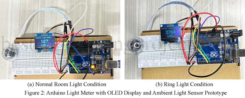
Ever found yourself squinting at a bright day, thinking, “How much light is actually hitting my face?” Well, using an Arduino light meter that guesswork is gone. You’re practically giving your Arduino a pair of shades, but this one isn’t there to block the light-it’s there to measure it. Sounds cool, right? Let’s dive in.
Why Build a Light Meter?
Imagine having a gadget that tells you how bright your workspace is, or whether your plants are getting enough sunlight. That’s the power of this little project. Using an ambient light sensor and an OLED display, we’ll create a device that can measure light levels and show them in real time. Perfect for a DIY enthusiast or someone just looking for a weekend project.
What You’ll Need
Here’s your shopping list for this project:
- Arduino Uno – Our main brain.
- 128×64 OLED Display (I2C) – Where the light readings will shine bright.
- DFRobot Ambient Light Sensor (0-200klx) – The light detective.
- Some jumper wires, a breadboard, and a sprinkle of patience.
Grab these, and you’re good to go. Oh, and coffee. Don’t forget coffee.
The Circuit: Connecting the Dots
Wiring this up is like putting together Lego, but for grown-ups.
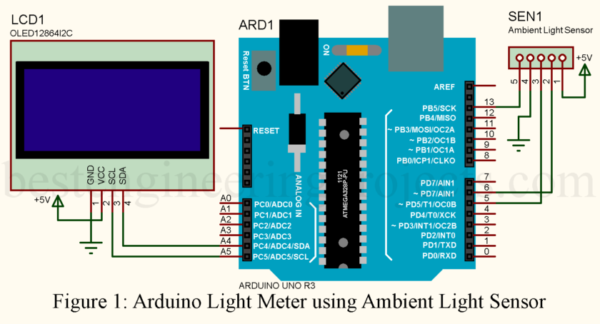
- Connect the OLED display’s SDA and SCL pins to A4 and A5 on the Arduino.
- The ambient light sensor gets its own SDA (pin 5) and SCL (pin 6). This avoids I2C clashes.
- Don’t forget the power! Both the OLED and the sensor need 5V and GND.
Here’s the diagram to make it clearer than a sunny day:
The Secret Sauce: Fixing I2C Conflicts
Now let me share with you a secret: If you connect the light sensor and OLED to the same I2C Pins. It stops working, and you’re sitting scratching your head.
How is it fixed? Quite simple. We utilize software I2C and give the sensor custom pins. It’s almost like giving it its very own private channel to talk to the Arduino.
Here’s the magic code:
|
1 |
DFRobot_B_LUX_V30B myLux(13, 6, 5); |
What’s happening here? We’re telling the sensor to use pins 6 and 5 for communication. Problem solved. Boom.
Writing the Code
Now comes the fun part—coding. Below is a snippet to get you started:
|
1 2 3 4 5 6 7 8 9 10 11 12 13 14 15 16 17 18 19 20 21 22 23 24 25 26 27 28 29 30 31 32 33 34 35 36 37 38 39 40 41 42 43 44 45 46 47 48 49 50 51 52 53 54 55 56 |
#include <Wire.h> #include <Adafruit_GFX.h> #include <Adafruit_SH110X.h> #include <DFRobot_B_LUX_V30B.h> DFRobot_B_LUX_V30B myLux(13, 6, 5); #define i2c_Address 0x3c #define SCREEN_WIDTH 128 #define SCREEN_HEIGHT 64 Adafruit_SH1106G display = Adafruit_SH1106G(SCREEN_WIDTH, SCREEN_HEIGHT, &Wire); void setup() { myLux.begin(); delay(250); // Wait for the OLED to power up display.begin(i2c_Address, true); // Address 0x3C default display.clearDisplay(); } void loop() { display.setTextColor(SH110X_WHITE); display.clearDisplay(); // Display title at the top display.setTextSize(1); display.setCursor(0, 0); display.println("Digital Light Meter"); // Get light value as integer int luxValue = (int)myLux.lightStrengthLux(); // Convert light value to string for alignment String luxString = String(luxValue); // Dynamically center light value int16_t x1, y1; uint16_t textWidth, textHeight; display.setTextSize(3); // Light value in size 3 display.getTextBounds(luxString, 0, 0, &x1, &y1, &textWidth, &textHeight); int16_t xValuePosition = (SCREEN_WIDTH - textWidth) / 2; // Center align display.setCursor(xValuePosition, 20); display.println(luxString); // Display the light value // Dynamically center "LUX." below the light value String luxUnit = "LUX."; display.setTextSize(2); // Smaller size for "LUX." display.getTextBounds(luxUnit, 0, 0, &x1, &y1, &textWidth, &textHeight); int16_t xUnitPosition = (SCREEN_WIDTH - textWidth) / 2; // Center align display.setCursor(xUnitPosition, 50); // Position below light value display.println(luxUnit); display.display(); delay(1000); } |
Breaking Down the Code
Dynamic Centering:
- We calculate the width of the text (getTextBounds) and adjust the cursor so the numbers sit smack in the middle of the screen.
- Whether the lux value is 23 or 1234, it’ll always look perfectly aligned. Smooth, right?
Big and Bold Design:
- The lux value is displayed in size 3 font, while “LUX.” sits beneath in a smaller, size 2 font.
- The design is clean, modern, and easy on the eyes.
This code initializes the OLED and the light sensor, then continuously reads and displays the light intensity. Don’t worry if it feels daunting—it’s like riding a bike—awkward at first but smooth once you get the hang of it.
Applications: Why This Matters
So, what can you do with a light meter? A lot more than you think:
- Check the light levels in your room for better productivity.
- Monitor sunlight for your indoor plants.
- Build it into a robot that adjusts lighting automatically.
It’s a simple project, but your imagination only limits its uses.
Wrapping It Up
An Arduino light meter isn’t just fun to make, but it’s a great opportunity to learn, fiddle, and create something useful. It may satisfy the interest levels of beginners or pros in such projects.
Get your parts, brew that coffee, and let’s measure the light like pros. And hey-don’t forget to show us your results!

