An amplifier that only amplify audio frequency range (typically 20Hz to 20K Hz) and attenuates all other range frequency range is called an audio amplifier. So, here in this post you will learn about power amplifier IC and at last we will design a 10-Watt Audio Amplifier Circuit with Volume Control using power amplifier IC with the features of volume control. We had already posted various amplifier circuit you may like.
- 7-Watt Audio Amplifier using TBA810
- 10-Watt Audio Amplifier using Transistor
- 20-Watt Audio Amplifier using TDA2020
- 20-Watt Audio Amplifier using TDA2003
- Audio Amplifier using 555 Timer IC
- Low Power Audio Amplifier Using LM386
- 8W + 8W Stereo Amplifier
At first Let’s discuss about what is audio power amplifier IC?
IC Power amplifier generally range up-to 40 Watts. Most of these types of IC is designed for class B operation, requiring that two stage to be used in Push-Pull amplifier circuit, such as in commonly found in audio output amplifiers. These, types of amplifiers generally have an external heat sink to dissipate the relatively large heat rise.
Let’s see the key parameters of Audio Amplifier IC
- Output Power: Typically, up to 40-watts, but the output power of IC we are using to design 10-watt Audio Power Amplifier can deliver up to 30-watts depending upon the input voltage and output load impedance.
- Maximum Power Dissipation: Typically, from 2 to 25 watts, but in the case if IC we are used (LM1875). The power dissipation at 15V is 1.5W, which increases with the increased in supply voltage. (maximum power dissipation is 6W at 60V supply voltage).
- Thermal Resistance: The junction-to-case temperature variation as a junction of power dissipation changes. A typical value will be 40C per watt. But, in the case of IC LM1875 thermal resistance values at 1500C for ambient temperature is about 4.20C per watt.
Application of Audio Power Amplifier IC
Most frequently found in audio output amplifiers as the final stage to drive a loudspeaker. This type of IC is also used in some servo-motor driving application
Things to be consider while using this type of IC
The heat sink mounting and heat dissipation of an IC power amplifier are its most critical performance characteristics. Many power amplifiers have automatic shut-down circuits to protect the IC when the temperature limit is reached. Short-circuit and over-voltage protection are also often included in the power amplifier IC.
Now let’s design a 10 watt audio amplifier circuit
Circuit Description and Working of 10-Watt Audio amplifier Circuit with Volume Control
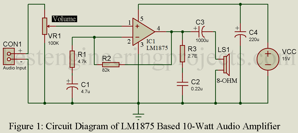
The circuit of 10-Watt audio amplifier is shown in figure 1, designed around amplifier IC LM1875, and few other passive components like resistor, capacitor, variable resistor and loudspeaker. According to datasheet of LM1875, it delivers output power of about 30W depends upon the input supply voltage and output load impedance.
Audio output from preamplifier or from mobile, PC or any other source (must be pre-amplified output) is given to non-inverting pin (pin 1) of IC1 though variable resistor (VR1). Here, this variable resistor is used in order to control the volume of amplifier output. Where inverting pin (pin 2) is grounded through resistor and capacitor. As we know that operational amplifier is negative feedback device thus we had used a feedback resistor which is connected between inverting pin and output as shown in circuit diagram.
For stability we had used a series network build using resistor and capacitor (R3 and C2) at the output pin as shown in circuit diagram. Finally, connected a loudspeaker (8-OHM, 10-Watt) though a capacitor (C3), this is used in order to filter out DC component if any available.
You can use power supply according to output power required from the range of 5V to 15V DC.
PARTS LIST OF 10-WATT AUDIO AMPLIFIER CIRCUIT WITH VOLUME CONTROL
| Resistor (all ¼-watt, ± 5% Carbon Unless Stated Otherwise) |
| R1 = 4.7 KΩ
R2 = 82 KΩ R3 = 2.7 Ω VR1 = 100 KΩ (Trimmer) |
| Capacitors |
| C1 = 4.7 µF, 25V (Electrolytic Capacitor)
C2 = 0.22 µF (Ceramic Disc) C3 = 1000 µF, 35V (Electrolytic Capacitor) C4 = 220 µF, 35V (Electrolytic Capacitor) |
| Semiconductor |
| IC1 = LM1875 (Audio Amplifier IC) |
| Miscellaneous |
| LS1 = 8Ω, 10-W Loudspeaker
Two, Two-point connector for audio input and loudspeaker Heat-Sink for IC LM1875 |
