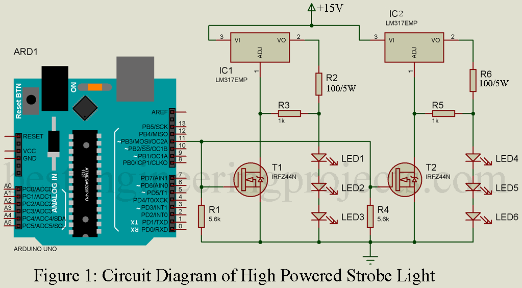
The project High Powered Strobe Light Using Arduino is the extended version of strobe light using arduino. Here, in this project we uses six high power Luxeon LED as used in previous project. This project show different strobe effect like flashing, fading, continuous illuminating etc. We can select any of this effect through serial monitor. Lets see the circuit diagram and how its work.
Circuit Description of High Powered Strobe Light Using Arduino
The circuit is shown in figure 1 and is designed around arduino uno board, N-Channel MOSFET, LM317 Variable voltage regulator and few other components as shown in circuit diagram.
Control circuit is designed using arduino and MOSFET. Due to fading effect we have to use PWM pin instead of normal digital PIN with analogwrite() in order to trigger MOSFET. Two resistors R1 and R4 ground the Gate to ground in order to avoid false triggering. Source pin of MOSFETs is connected to ground where drain pin is connected to adjustment pin of variable voltage regulator IC. Current limiting resistor of 4-ohm/1W is connected in series with LEDs arranged in column as shown in circuit diagram. For powering the LED we are using LM317 variable voltage regulator IC.
Let’s do some mathematical calculation
We had designed this circuit for LXML-PWC1-0100 LUXEON LED.
Voltage required to illuminate LED i.e. Vin
Here we are using three LED in series, hence number of LED nLED = 3
(voltage required to powering the single LED)
Now, wee can calculate the Vin voltage
So, we required approximately 14V per column.
After calculating required voltage for powering the LED, let’s calculate supply voltage by LM317
So the value for resistor R3 and R5 = 1000-ohm
and value for R2 and R6 = 100-ohm/5Watt
Check this video on designing Adjustable Power Supply Circuit using LM317 IC.
Components List
| Resistor (all ¼-watt, ± 5% Carbon) |
| R1, R2, R4 = 1 KΩ
R3, R5 = 100 Ω/5W |
| Semiconductors |
| Arduino Uno or clone
IC1, IC2 = LM317 T1, T2 = IRFZ44N LED1 – LED6 = LXML-PWC1-0100 LUXEON |
Software Code:- Software code for High Powered Strobe Light Using Arduino is written in arduino programming language and compiled using arduino IDE. You do not need to modify the the software code part unless you do change in circuit part. Upload the code to your arduino board and open serial monitor. Send the command like ‘w’, ‘s’ or any digits from ‘0 to 9’ and observe the difference.
|
1 2 3 4 5 6 7 8 9 10 11 12 13 14 15 16 17 18 19 20 21 22 23 24 25 26 27 28 29 30 31 32 33 34 35 36 37 38 39 40 41 42 43 44 45 46 47 48 49 50 51 52 53 54 55 56 57 58 59 60 61 62 63 64 65 |
int ledPin = 11; int period = 100; char mode = 'o'; // o-off, s-strobe, w-wave void setup() { pinMode(ledPin, OUTPUT); analogWrite(ledPin, 255); Serial.begin(9600); } void loop() { if (Serial.available()) { char ch = Serial.read(); if (ch == '0') { mode = 0; analogWrite(ledPin, 255); } else if (ch > '0' && ch <= '9') { setPeriod(ch); } else if (ch == 'w' || ch == 's') { mode = ch; } } if (mode == 'w') { waveLoop(); } else if (mode == 's') { strobeLoop(); } } void setPeriod(char ch) { int period1to9 = 9 - (ch - '0'); period = map(period1to9, 0, 9, 50, 500); } void waveLoop() { static float angle = 0.0; angle = angle + 0.01; if (angle > 3.142) { angle = 0; } analogWrite(ledPin, (int)255 * sin(angle)); delay(period / 100); } void strobeLoop() { analogWrite(ledPin, 255); delay(10); analogWrite(ledPin, 0); delay(period); } |
NOTE: This project is originally published on 10 NOV 2015 and updated on 1 March 2019
