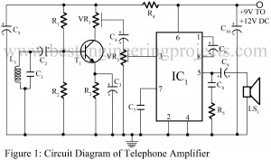
Telephone talks are meant to be private or kept in between two persons engaged in the conversation. But, sometimes it is also necessary to have a group talk. The project entitled Telephone amplifier circuit serves us right. It is very simple, yet inexpensive and useful which uses very common power amplifier LM386 and some more components. The circuit can be used to produce loud sound to discuss or start a conversation in a group through telephone. Working of the Telephone Amplifier Circuit The signal emitted as output from telephone is…
Read MoreCategory: Amplifier Circuit
Bass Booster Circuit using Op-Amp 741 IC
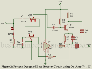
Here is one another basic project call bass booster using op-amp 741 IC. The circuit bass booster increases beat frequency without affecting high frequency. Description of Bass Booster Circuit using Op-Amp 741 IC The circuit of bass booster shown in figure 1 is divided into two main section i.e. bypass high frequency and boost section. The input of this circuit is connected to the output of pre-amplifier circuit and it’s output to input of power amplifier circuit. When audio signal is given to the input, high frequency is passed through…
Read MoreDIY Headphone Amplifier using 741 IC
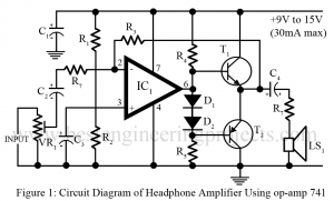
Various type of amplifier and pre-amplifier circuit has appeared in this website in amplifier and pre-amplifier section. The circuit posted here is of DIY headphone amplifier which is suitable for headphone or 8-ohm speaker or more impedance. The circuit is so designed that it has no risk of overloading or distortion of either the circuit or headphone. Circuit Description DIY Headphone Amplifier using 741 IC The heart of the circuit headphone amplifier is op-amp 741 which provide suitable gain where the transistor T1 and T2 are used to drive low…
Read More8W + 8W Stereo Amplifier Circuit with Graphic Equalisers
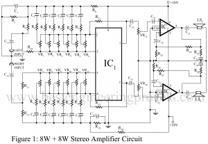
Various kinds of stereo amplifier are readily available in market. But if we ask for good quality stereo amplifier with graphic equaliser facility, it’s price become very high. The cheaper varieties are generally based on discrete transistors, and suffer from drawback such as uncontrolled hum, ineffective tone control, poor base response, thermal runway etc. the use of inter-stage transformers in such circuits reduces their versatility. Here you find the tutorial to build 8W + 8W Stereo Amplifier with Graphic Equalisers. Features | 8W + 8W Stereo Amplifier Circuit with Graphic Equalisers…
Read More20W Audio Amplifier Using TDA2020
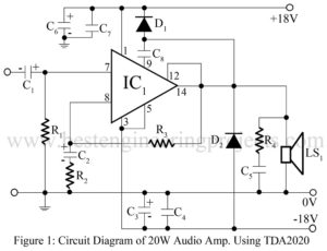
20W Audio Amplifier Using TDA2020 Here is one another circuit in the series of audio power amplifier. We had already posted audio amplifier using transistor (3Watt, 10Watt and 20Watt) and using IC (7Watt and 20Watt). We used here IC TDA2020 for designing audio amplifier circuit. TDA2020 (IC1) can deliver a maximum of 20Watt into a 4Ω loads. Like the TBA810, the TDA2020 also incorporated thermal shutdown, and output short-circuit protection. The input impedance of the circuit 20Watt audio amplifier using TDA2020 is determined by resistor R1 and sensitivity is determined…
Read More7W audio amplifier using TBA810
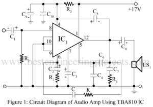
Here is another circuit in the series of audio power amplifiers. Previously we had already posted 3W and 20W audio amplifiers using transistors. Now we use an integrated circuit instead of transistors for designing audio amplifier circuits. By using IC TBA810 one can get a power output of 7W. The audio power amplifier featuring the TBA810 integrated circuit is shown in figure 1. This IC incorporated build-in-terminal shutdown, which automatically reduces the output in the event of sustained overloads or if the heat sinking arrangement is inadequate. We use a…
Read More20W Audio Amplifier Using ECN149-ECP149 Pair Transistor
High wattage power transistor is matched complementary pair are now readily available. Using such transistor, an economical high power amplifier using a minimum of components and giving a good performance can easily by constructed by an audio enthusiast. Thus, here we had designed a 20W Audio Amplifier Using ECN149-ECP149 Pair Transistor. Circuit Description of 20W Audio Amplifier Using Ecn149-ECP149 Pair Transistor A discrete power amplifier circuit is shown in figure 1 employs the 30W silicon output transistor pair ECN149-ECOP49. This amplifier will deliver 20W into 8Ωwith a 450mV input signal. We…
Read More3watt Audio Amplifier Using AC187-AC188 Pair
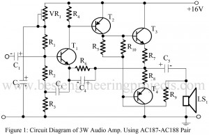
The high wattage power transistor with matched complementary pair is now readily available. Using such a transistor, an economical high power amplifier using a minimum of components and giving a good performance can easily be constructed by an audio enthusiast. Here in this article, we are going to build a 3watt audio amplifier by using complementary pair of transistors. Circuit Diagram of 3watt Audio Amplifier Using AC187-AC188 Pair A discrete 3watt Audio power amplifier circuit is shown in figure 1 employs a complementary output stage featuring the AC 187-AC188 (T3…
Read MoreGuitar Amplifier | Convert Hawain Guitar to an Electric Guitar
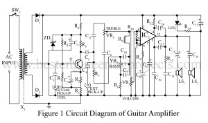
Whereas an electric guitar with 60W PMPO (Peak Music Power Output) costs around $8, here is a cost effective solution to convert a Hawain guitar to an electric guitar. The circuit Guitar Amplifier | Convert Hawain Guitar to an Electric Guitar can also be used as an ampli-speaker with a tape recorder or a radio receiver. Circuit Description of Guitar Amplifier | Convert Hawain Guitar to an Electric Guitar The unit can easily be assembled on a standard TBA810 ampli-speaker PCB available in the market. It is also be housed in…
Read MoreVideo Distribution Amplifier
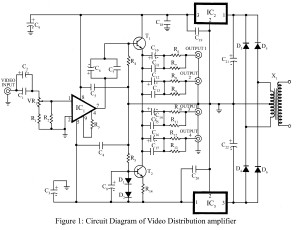
Distribution of Video to various recorders or TVs without losses or distortion is quite difficult. Thus, in order to solve this problem we had posted the project video distribution amplifier During the distribution of the video some losses and distortion might occur to decrease the quality of the video, but don’t worry here is a simple electronics project to overcome the problem, This video distribution amplifier enables four video recorders or TVs to be connected to the output of one VCR or VCP. The circuit “Video Distribution Amplifier” can be…
Read More