Codes and raw digital data are being transmitted with increasing volume every year. Unless some means of code error detection are used, it is not possible to know when errors have occurred. These errors are caused by noise and transmission system impairments. In contrast, it is obvious when a voice transmission has been impaired by noise or equipment problems.
Redundancy is used as the means of error detection when codes and digital data are transmitted. A basic redundancy system is to transmit everything twice and to make sure that an exact correlation exists. Fortunately, schemes have been developed that do not require such a high degree of redundancy.
Parity | Code Error Detection and Correction
The most common method of error detection is the use of parity. A single bit called the parity bit is added to each code representation. If it makes the total number of l’s even, it is termed even parity, and an odd number of l’s is odd parity. For example, if the ASCII code for A is to be generated, the code is P1000001 and P is the parity bit. Odd parity would be 11000001 since the number of l’s is now 3. The receiver checks for parity. If an even number of l’s occurs in a character grouping (word), an error is indicated and the receiver usually requests retransmission. Unfortunately, if two errors (an even number) occur, parity systems will not indicate an error. In many systems a burst of noise causes two or more errors, so more elaborate error-detection schemes may be required.
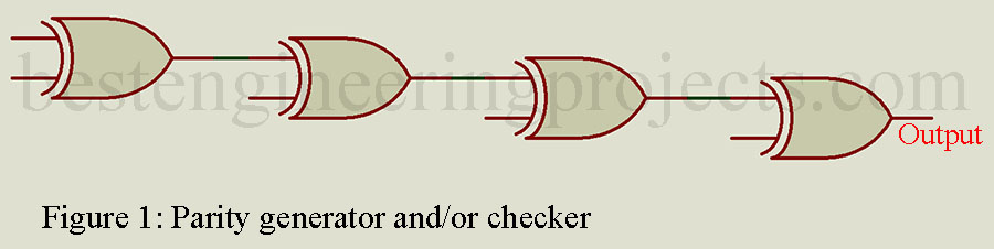
There are many circuits used as parity generators and/or checkers. A simple technique is shown in Fig. 1. If there are n bits per word, n – 1 Exclusive-OR (XOR) gates are needed. The first two bits are applied to the first gate and the remaining individual bits to each subsequent gate. The output of this circuit will always be a 1 if there is an odd number of l’s and a 0 output for an even number of l’s. If odd parity is desired, the output is fed through an inverter. When used as a parity checker, the word and parity bit are applied to the inputs. If no errors are detected, the output is low for even parity and high for odd parity.
When an error is detected there are two basic system alternatives:
- An automatic request for retransmission.
- Display of an unused symbol for the character with a parity error (called symbol substitution)
Most systems use a request for a repeat system. A block of data is transmitted-if no error is detected, a positive acknowledgment (ACK) is sent back to the transmitter. If a parity error is detected, a negative acknowledgment (NAK) is made and the transmitter repeats that block of data. Exactly what happens after error detection falls under the subject of protocols.
A more sophisticated method of error detection than simple parity is needed in high-data-rate systems (typically, 2400 b/s and above). At these speeds, telephone data transmission is usually synchronous and blocking. A block is a group of characters transmitted with no time gap between them. It is followed by an end of message (EOM) indicator and then a block check character (BCC). Block size is typically 256 characters. The transmitter uses a predefined algorithm to compute the BCC. The same algorithm is used at the receiver based on the block of data received. The two BCCs are compared, and if identical, the next block of data is transmitted.
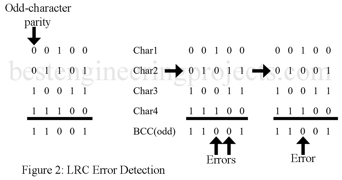
There are many algorithms used to generate a BCC. The most elementary one is an extension of parity into two dimensions, called the longitudinal redundancy check (LRC). This method is illustrated with the help of Fig. 2. Shown is a small block of 4-bit characters using odd parity. The BCC is formed as an odd-parity bit for each vertical column. Now suppose that a double error occurred in character 2 as shown in Fig. 2(b). As described previously, simple parity would not pick up this error. With the BCC, however, the error is detected. If a single error occurs [Fig. 2(c)], the erroneous bit can be pinpointed as the intersection of the row and column containing the error.
The error location process just described is not usually utilized. Rather, the receiver checks for character and LRC errors, and if either (or both) occur, a retransmission is requested. Occasionally, an error will occur in the BCC. This is unavoidable, but the only negative consequence is occasional unnecessary retransmission.
Cyclic Redundancy Check | Code Error Detection and Correction
A more sophisticated set of algorithms than parity schemes for BCC calculation is the cyclic redundancy check (CRC). It is easily the most powerful code error detection technique in common use. The entire message block is treated as a long binary number. The binary division is performed by some binary constant and the remainders are subsequently compared at the receiver. A difference between the remainder transmitted by the transmitter and generated at the receiver causes that message block to be retransmitted. The division process usually involves special 12- or 16-bit shift registers at the transmitter and receiver. The CRC technique does not burden the transmitter with the continuous sending of parity bits and thus offers more efficient data transmission. The CRC pattern is only 16 bits or less, and it need only be sent at the end of blocks containing several thousand bits.
Hamming Code
The error-detection schemes thus far presented require retransmission if errors occur. Techniques that allow correction at the receiver are called forward error-correcting (FEC) codes. The basic requirement of such codes is for sufficient redundancy so as to allow error correction without further input from the transmitter. The Hamming code is an example of an FEC code named for R. W. Hamming, an early developer of error detection/correction systems.
If m represents the number of bits in a data string and n represents the number of bits in the Hamming code, n must be the smallest number such that

Consider a 4-bit data word 1101. The minimum number of parity bits to be used is 3 when Eq. (9-6) is referenced. A possible setup, then, is
P1 P2 1 P3 1 0 1
1 2 3 4 5 6 7 bit location
We’ll let the first parity bit, P1, provide even parity for bit locations 3, 5, and 7. P2 does the same for 3, 6, and 7, while P3 checks 5, 6, and 7. The resulting word, then, is
1 0 1 0 1 0 1
1 2 3 4 5 6 7 bit location
P1 P2 P3
When checked, a 1 is assigned to incorrect parity bits, while a 0 represents a correct parity bit. If an error occurs so that bit location 5 becomes a 0, the following process takes place. P1 is a 1 and indicates an error. It is given a value of 1 at the receiver. P2 is not concerned with bit location 5 and is correct and therefore given a value of 0. P3 is incorrect and is therefore assigned a value of 1. These three values result in the binary word 101. Its decimal value is 5, and this means that bit location 5 has the wrong value and the receiver has pinpointed the error without retransmission. It then changes the value of bit location 5 and transmission continues. The Hamming code is not able to detect multiple errors in a single data block. More complex (and more redundant) codes are available if necessary.