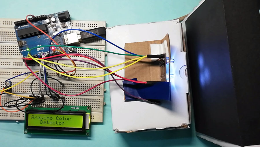
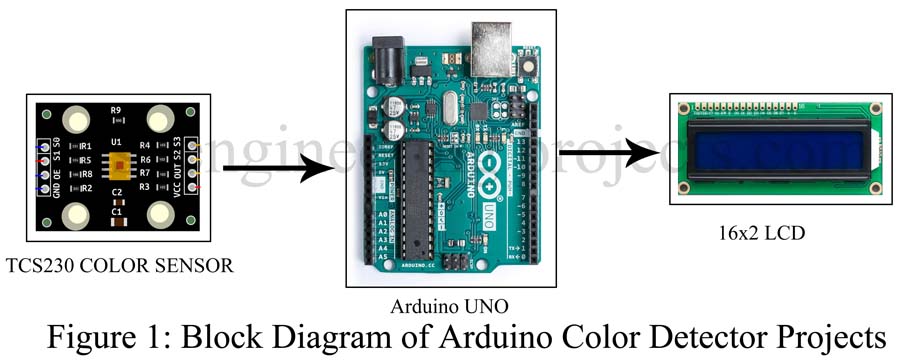
This article shows you how to make arduino color sensor project using TCS230 color sensor. This project can detect almost all color according to their wave length and display it on 16×2 LCD. If we talk about the application of this project, you can use in color shorting or color matching projects, line following robot (if path is other than black and white), multi-color strip reading etc.
What is TCS230 Color Sensor?
This module consists 8×8 array of photodiode which detect the color and produce corresponding frequency (Square wave). So, we can say that color sensor module TCS230 is light to frequency converter. As the frequency is of square wave type arduino can read it through its digital pin directly i.e. we do not need ADC. There are total number of 64 photodiode (8×8 = 64) which is divided into for color category i.e. RED Filter, GREEN Filter, BLUE Filter and no COLOR Filter. Each category consists 16 numbers of photodiode. This photo diode generate frequency according to color it detects.
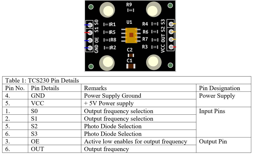
At first let’s see the pin configuration of TCS230. Thera are total 8 numbers of pin out of which two are for power supply pin and 6 are for input and output pin.
Working principle of detecting the color
The three colors Red, Blue and Green (RGB) wavelengths are known as primary colors because these can be combined or added together in different proportions to produce almost all other colors. Let’s take an example, white light can be produced by mixing 30% red, 59% Green and 11% blue. Similarly, all other colors can be produced by suitably mixing the primary colors as shown in figure below.
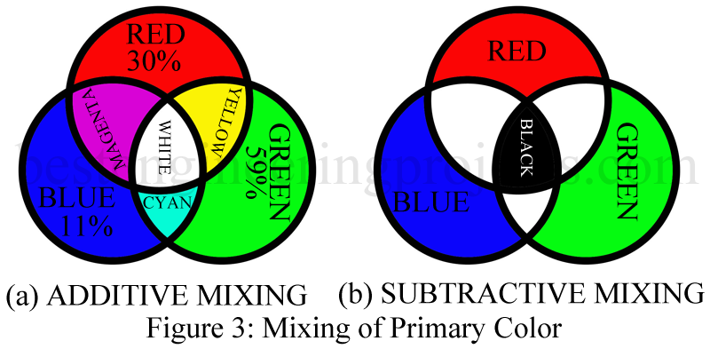
From above we can conclude that every other color is either additive mixture or subtractive mixture of these three-primary color. By using this same method, we are going to detect multiple color. In order to read these colors, we have to see the nature of output from pin S2 and S3. So, for easy understanding let’s make a truth table for color detection.
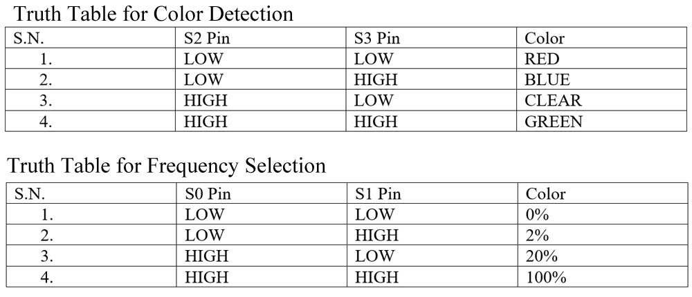
The value output from these two pins is mapped to 256 i.e. o to 255. The value from each color determine the color it detects. Now it’s time to set the frequency. Input pin S0 and S1 do this job. By using these two pins we can set the frequency to 0%, 2%, 20% and 100%. Let’s see the truth table of for frequency selection switch.
For the project Arduino Color Sensor Project, the frequency is set to 20%, this can be done in software code. You have to assign HIGH for S0 pin and LOW for S1.
Circuit Description of Arduino Color Sensor Project
The circuit is shown in figure 2. build around Arduino uno board, TCS230 Color sensor and 16×2 LCD. VCC pin of TCS230 is connected to +5V arduino supply where GND and OE pin is connected to ground. Frequency selection pin S0 and S1 is connected to arduino uno digital pin D2 and D3. Color Pin S2 and S3 is connected to arduino pin DD4 and D5 where the output pin (OUT) is connected to arduino D6.
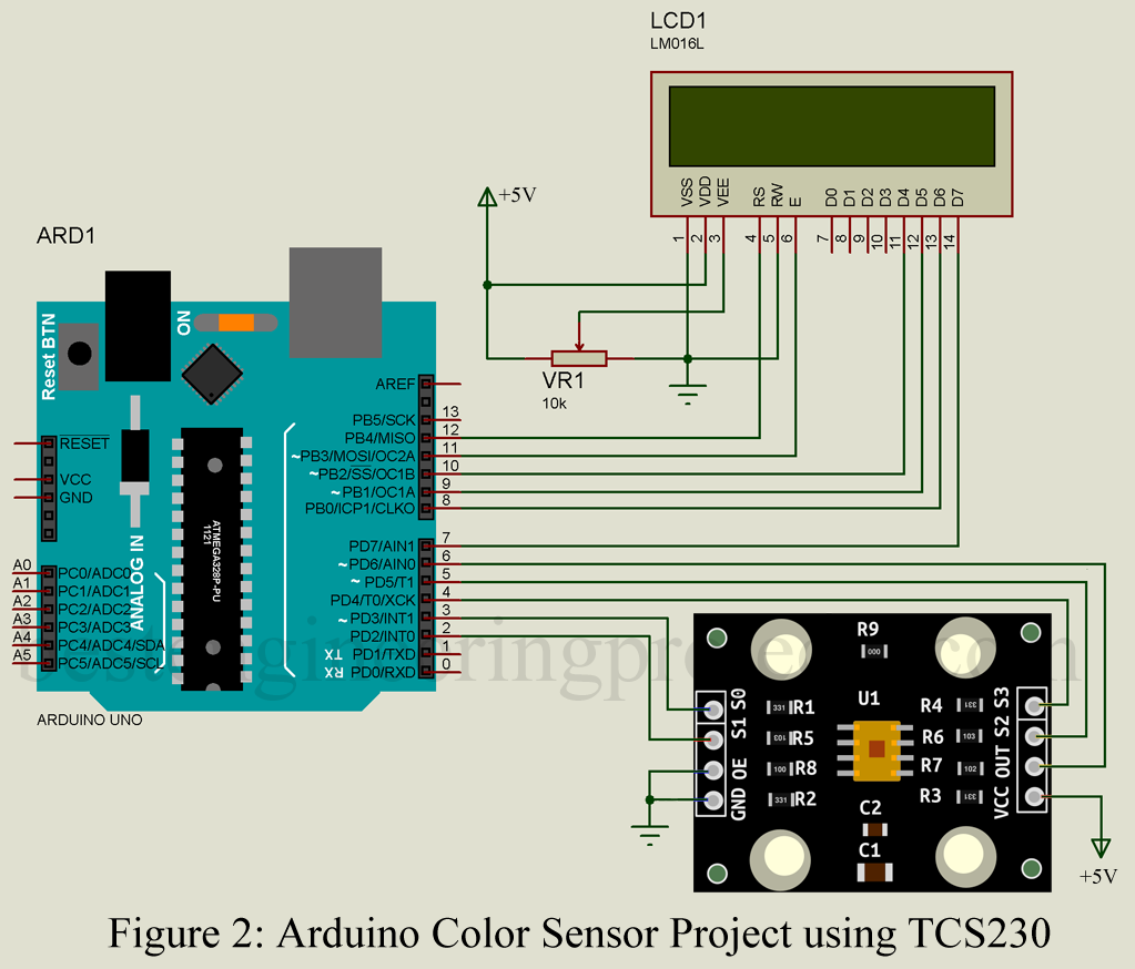
LCD is connected in 4-bit higher order data bit i.e. only higher data pin D4 to D7 of LCD is used to communicate with LCD. Four higher order data bit D4, D5, D6 and D7 is connected to arduino D10, D9, D8 and D7 respectively where RS and E pin is connected to D12 and D11 pin of arduino as shown in circuit diagram. VSS, RW and LED- pin is connected to GND, where VDD pin is connected to +5V power supply. VEE pin must be at lower potential than VDD but higher than VSS and this pin is responsible for contrast control.
If you are new to arduino and LCD interface then please do watch this video on “Interfacing of 16×2 LCD with Arduino”.
Software code: Software code for this project is written in arduino programming language and compiled using arduino IDE.
|
1 2 3 4 5 6 7 8 9 10 11 12 13 14 15 16 17 18 19 20 21 22 23 24 25 26 27 28 29 30 31 32 33 34 35 36 37 38 39 40 41 42 43 44 45 46 47 48 49 50 51 52 53 54 55 56 57 58 59 60 61 62 63 64 65 66 67 68 69 70 71 72 73 74 75 76 77 78 79 80 81 82 83 84 85 86 87 88 89 90 91 92 93 94 95 96 97 98 99 100 101 102 103 104 105 106 107 108 109 110 111 112 113 114 115 116 117 118 119 120 121 122 123 124 125 126 127 128 129 130 131 132 133 134 135 136 137 138 139 140 141 142 143 144 |
/* Pin Difination for TCS230 Color Sensor*/ #define S0 2 //SO pin to arduino D2 pin #define S1 3 //S1 pin to arduino D3 pin #define S2 4 //S2 pin to arduino D4 pin #define S3 5 //S3 pin to arduino D5 pin #define OP 6 //Output pin to arduino D6 pin /*Initialling the value of variable to 0*/ int R = 0; //Initial value of RED Color is 0 int B = 0; //Initial value of BLUE Color is 0 int G = 0; //Initial value of GREEN Color is 0 unsigned int frequency1 = 0; //Initial frequency for RED is 0 unsigned int frequency2 = 0; //Initial frequency for BLUE is 0 unsigned int frequency3 = 0; //Initial frequency for GREEN is 0 #include <LiquidCrystal.h> LiquidCrystal lcd(12, 11, 10, 9, 8, 7);//RS,EN,D4,D5,D6,D7 //Function setup starthere void setup() { lcd.begin(16, 2); pinMode(S0, OUTPUT); //Assigning arduino pin D2 as output pinMode(S1, OUTPUT); //Assigning arduino pin D3 as output pinMode(S2, OUTPUT); //Assigning arduino pin D4 as output pinMode(S3, OUTPUT); //Assigning arduino pin D5 as output pinMode(OP, INPUT); //Assigning arduino pin D6 as input /*Frequency is set for 20% so according to truth table SO pin must be at high potential and S1 pin at low potential*/ digitalWrite(S0,HIGH); //Making arduino pin D2 HIGH (+5V) digitalWrite(S1,LOW); //Making arduino pin D3 LOW (GND) Serial.begin(9600); //Baud rate for serial communication //use only when you use seraial monitor to see output lcd.setCursor(0,0); lcd.print("Arduino Color"); lcd.setCursor(0,1); lcd.print(" Detector "); delay(2000); lcd.clear(); } //Function setup end here //Function Loop Start here void loop() { /*checking for red color*/ digitalWrite(S2,LOW); //Making arduino pin D4 LOW (GND) digitalWrite(S3,LOW); //Making arduino pin D5 LOW (GND) frequency1 = pulseIn(OP, LOW); //Reading frequency for RED using pulseIN function Serial.print("R="); Serial.println(frequency1); //Displaying frequency of RED on serial monitr R = frequency1; //assigning value of Red frequiency to R delay(50); // 50 milli seconds delay /*checking for blue color*/ digitalWrite(S2,LOW); digitalWrite(S3,HIGH);// setting for BLUE color sensor frequency2 = pulseIn(OP, LOW);//Reading frequency for BLUE using pulseIN function Serial.print("B="); Serial.println(frequency2); //Displaying frequency of BLUE on serial monitr B = frequency2; //assigning value of BLUE frequiency to B delay(50); // 50 milli seconds delay /*checking for green color*/ digitalWrite(S2,HIGH); digitalWrite(S3,HIGH);// setting for GREEN color sensor frequency3 = pulseIn(OP, LOW); //Reading frequency for GREEN using pulseIN function Serial.print("G="); Serial.println(frequency3); //Displaying frequency of GREEN on serial monitr G = frequency3; //assigning value of GREEN frequiency to G delay(50); // 50 milli seconds delay Serial.println("stop"); /*Change the value of R, B and G with the value you have measured */ /*Checking for RED color if the value of R and G lies between below defined value LCD display RED color*/ if(R<90 & R>45 & G<185 & G>130) { lcd.setCursor(0,0); lcd.print(" RED "); } /*Checking for ORANGE color if the value of B and G lies between below defined value LCD display ORANGE color*/ if(G<155 & G>120 & B<155 &B>115) { lcd.setCursor(0,0); lcd.print("ORANGE"); } /*Checking for GREEN color if the value of R and G lies between below defined value LCD display GREEN color*/ if(R<150 & R>110 & G<160 & G>140) { lcd.setCursor(0,0); lcd.print(" GREEN"); } /*Checking for YELLOW color if the value of R and G lies between below defined value LCD display YELLOW color*/ if(R<80 & R>40 & G<120 & G>80) { lcd.setCursor(0,0); lcd.print("YELLOW"); } /*Checking for VOILET color if the value of R and G lies between below defined value LCD display VOILET color*/ if(R<90 & R>60 & B<110 & B>75) { lcd.setCursor(0,0); lcd.print("VOILET"); } /*Checking for MAGENTA color if the value of R and G lies between below defined value LCD display MAGENTA color*/ if(G<115 & G>80 & B<100 & B>50) { lcd.setCursor(0,0); lcd.print("MAGENTA"); } /*Checking for BLUE color if the value of B and G lies between below defined value LCD display BLUE color*/ if (G<235 & G>165 & B<190 &B>110) { lcd.setCursor(0,0); lcd.print(" BLUE "); } /*Checking for BLACK color if the value of B and G lies between below defined value LCD display BLACK color*/ if (R<200 & R>150 & G<270 &G>210) { lcd.setCursor(0,0); lcd.print(" BLACK "); } delay(2000); //2 second delay only for pause the screen lcd.clear(); // Clear the screen } // End of Loop Function |
Procedure of Arduino Color Sensor Projects
- Copy the above code in your arduino IDE, upload it in your Arduino board.
- Open serial monitor and place any color object in from of color senor TCS230.
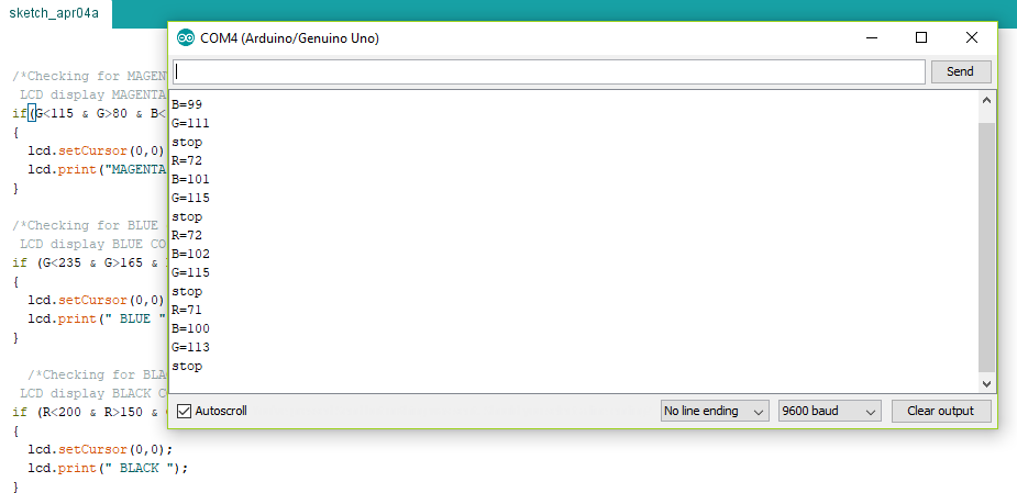
- There you will see different value of R, G, B.
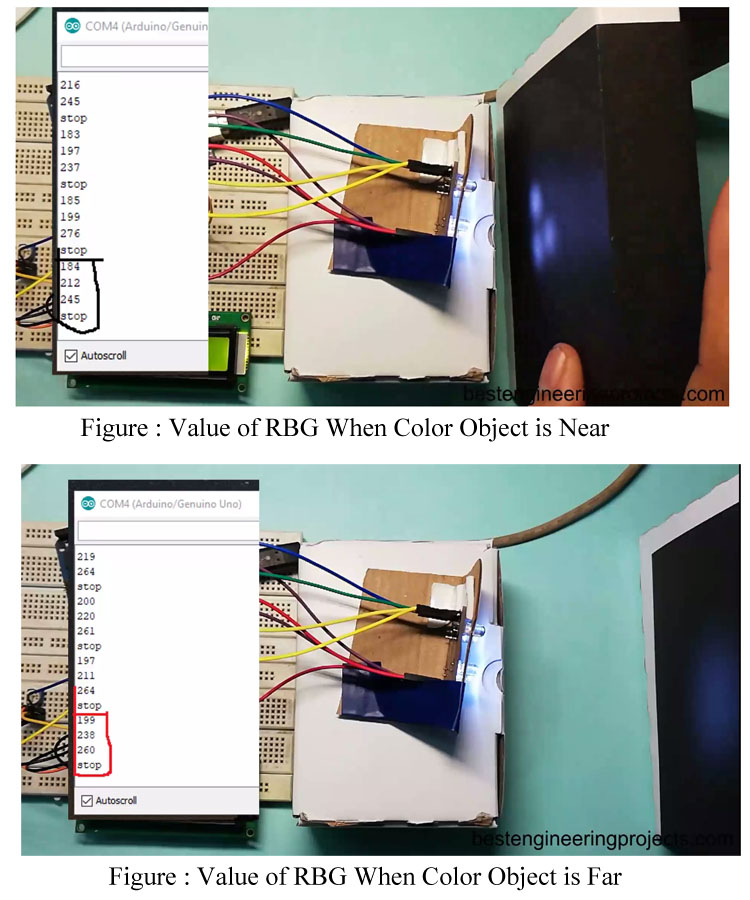
- At first, place the colored object near the color sensor and note down the value of R, B and G shown in serial monitor.
- Similarly, place the colored object far from the color sensor and note down the value of R, B and G shown in serial monitor.
- Follow the same procedure of previous step for different color.
- Now update the code with the value you have measured.
- Scroll down to color frequency comparing code and there update the previous value of R, B and G with the value you have measured.
Note: The value of R, B and G is different at different intensity of light i.e. it show different value of R, B and G for same color at dark and at light. The value of R, B and G might be different then the value used in code so please measure the color for specified object with your own color sensor.