In this article we will discuss about two different counter IC, Programmable and Up Down Counter IC. Programmable divide by N counter IC (F4526) and UP Down counter (SN74192). We will discuss about key parameter and applications. At first we will discuss about programmable divide by N counter and then Up Down Counter.
Programmable Divide by N Counter Description
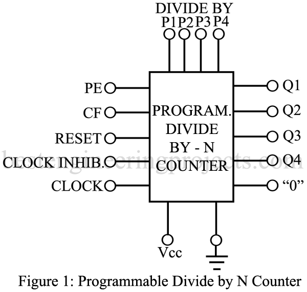
Each flip-flop (FF) in this counter can be programmed for either 0 or 1, allowing the user to determined the desired division of the input (clock) frequency. A set of program inputs and an enabling signal perform this task. In addition, the clock can be inhibited, there is a master reset input and a special cascade input and output terminal. As illustrated in figure 1, the cascade input terminal is marked CF (carry forward) while the output terminal is labeled 0. The PE terminal enables the programmable divide-by-N inputs P1 through P4 and the output appears on terminals Q1 through Q4. When larger numbers are to be divided down, several of these ICs can be cascaded without any additional logic. The clock inhibit input allows disabling of the pulse counting function.
Key Parameters of Programmable Divide by N Counter
The electrical characteristics are essentially the same as those of the particular digital IC family.
- Maximum clock frequency: Ranges from 3 to 6 MHz for CMOS devices and up to 50 MHz for TTL ICs.
- Minimum clock pulse width: Low-power CMOS devices generally use 80 to 250 ns, while TTL ICs can operate with clock pulse width of 25 ns.
- Minimum program enables pulse width: For low lower CMOS devices 80 to 250 ns is typical.
- Minimum master reset pulse width: Lower power CMOS devices require from 200 to 350 ns.
Applications
Programmable divide-by-N counters are particularly useful in frequency synthesizers phase-locked loops, and other frequency division applications.
Representative Part Number: Fairchild F4526
Comments
A variety of programmable or presettable counters is available. By presetting the stages of a counter, one can achieve timing because the counter can be made to reset or “fill up” when the preset count has been reached. Another application is to divide the input frequency by a preset or programmed number. Either function is available in a variety of different configurations.
Up Down Counter Description
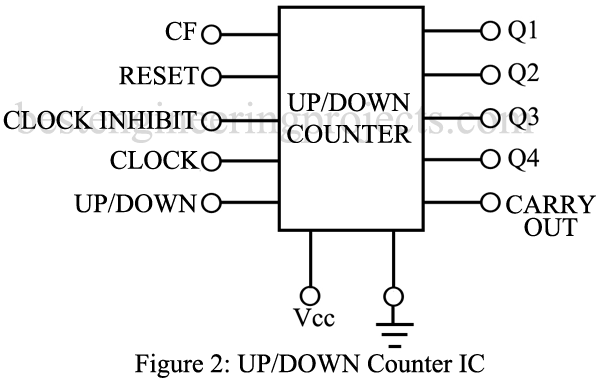
The key feature of this IC is the ability of an otherwise ordinary counter to count wither down or up. This makes it possible to enter a number of pulses during one period and then to subtract a second number from the first by counting down that number of pulses. While many up/down counters are programmable or presettable, the function block illustrated in figure 1 omits this feature and shows only the control necessary for the up and down counting operation and cascading. When the counter is full, the carryout terminal is used to feed the overflow into the next cascade IC. The CF terminal serves as input of either the original signal or the overflow from a previous cascaded section. A master reset, a clock inhibits, and a clock input are provided, but the key features is the up down mode control. When this terminal is at 1, the counter operates in a normal counting up mode. When the up down mode control is 0, the counter will count down.
Key Parameters of Up Down Counter
The electrical characteristics will be the same as for the particular digital IC family.
- Up down setup time: The time required to change counter operation from up to down or back to up. Typical values for low power CMOS range from 50 to 170 ns. For TTL devices, 20 to 30 ns is typical.
Applications
Whenever Up down counting capability is required. Widely used in difference counting and frequency synthesizer applications. This IC is also found in analog to digital and digital to analog converter systems and in computers to generate magnitudes and polarity signs.
Representative Part Number: Texas Instruments SN74192
Comments
Up Down counter are available with programmable inputs, with divide by N features, and with other capability.

