The field of communications now makes heavy use of the frequencies from 1 up to 300 GHz-we shall loosely refer to these as microwave frequencies. At microwave frequencies, even the shortest circuit connections must be carefully considered due to the extremely small wavelengths involved. The thin-film hybrid and monolithic integrated circuits used at microwave frequencies are called MICs (microwave integrated circuits). Check out the article on Applications of Microwaves
Microwave Integrated Circuit Overview
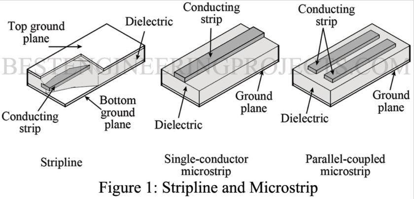
Obviously, the use of short chunks of coaxial transmission lines or waveguides is not practical for the required connections of mass-produced miniature circuits. Instead, either a stripline or microstrip connection is often used. They are shown in Fig. 1. They both lend themselves to mass-produced circuitry and can be thought of as a cross between waveguides and transmission lines with respect to their propagation characteristics.
The stripline consists of two ground planes (conductors) that “sandwich” a smaller conducting strip with constant separation by a dielectric material (printed circuit board). The two types of microstrip shown in Fig. 1 consist of either one or two conducting strips separated from a single ground plane by a dielectric. While stripline offers somewhat better performance due to lower radiation losses, the simpler and thus more economical microstrip is the prevalent construction technique.
In either case, the losses exceed those of either waveguides or coaxial transmission lines, but the miniaturization and cost savings far outweigh the loss considerations. This is especially true when very short connection paths are considered.
As with waveguides and transmission lines, the characteristic impedance of stripline and microstrip are determined by physical dimensions and the type of dielectric. The most often used dielectric is alumina with a relative dielectric constant of 9.6. Proper impedance matching, so as to minimize standing waves, is still an important consideration.
Figure 2 provides end views of the three lines. The formulas for calculating Zo for them are provided. In the formulas, In is the natural logarithm, and is the dielectric constant of the board.
Z0 for Stripline
Z0 for Single Conductor Microstrip
Z0 for Parallel Coupled Microstrip
Dielectric Waveguide
A more recent contender for “wiring” of miniature millimeter-wavelength circuits is the dielectric waveguide. Its operation is dependent on the principle that two dissimilar dielectrics have a guiding effect on electromagnetic waves.
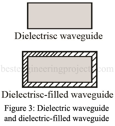
The dielectric waveguide should not be confused with the dielectric-filled waveguide. Both are shown in Fig. 3. A regular metallic waveguide is sometimes filled with dielectric, as this decreases the size necessary to allow propagation of a given frequency.
The dielectric waveguide is obviously easy to mass-produce within integrated circuits and offers an advantage over microstrip. At frequencies above 20 to 30 GHz, the losses with microstrip become excessive for many system applications as compared to the dielectric waveguide. For example, at 60 GHz microstrip typically attenuates 0.15 dB/cm, while the dielectric waveguide attenuates only 0.06 dB/cm. The figure for a standard rectangular waveguide at 60 GHz is about 0.02 dB/cm but would only be used in systems where cost is not a factor.
Alumina is commonly used as the dielectric material for dielectric waveguides. However, semiconductors such as silicon and gallium arsenide (GaAs) will undoubtedly be the dielectrics used in the future. This is dictated by the fact that ultimately semiconductor devices will be fabricated directly into the dielectric waveguide.


