The project “Arduino Fingerprint Sensor Lock” is simply fabricated around Arduino board. Not only to ensure door security, this project also make certain to assist in fields like forensics, crime investigation, personal identification, attendance system and there is a lot more.
Introduction of Arduino Fingerprint Sensor Lock
Recently, there has been recorded tremendous increase in the crime rate everywhere in the world. This issue is turning more severe every day. To get away with this problem, we decided to take help from technology and there this project “Arduino Fingerprint Sensor Lock” developed. We know the saying very well- ‘Prevention is better than cure’, rather than to face the loss it is much better to take necessary actions to eradicate that issue before it happens.
The project helps us to implement the fact. The reason behind the fact that project has gained so much popularity in a short interval is mostly because of its simplicity and attractive feature. Today, fingerprint project is linked with security and major task, later it may be employed as fingerprint based driving license, bank accounts operation and so on. ‘Matching Algorithm’ is the main principle of this project where specified templates of fingerprints are initially stored. Then, the fingerprint of user is compared with the pre-stored templates of fingerprints. It verifies authentication process.

The old practice of using a simple key to unlock a door is time consuming as well as less secure. Replacing those methods with fingerprints, we get access inside a house/room just by placing the correct finger on the sensor. However, only authorized people can open the door because of the special fingerprint technique. If the fingerprint matches with any one of the image from database, the door unlocks and the LCD displays a welcome message along with that person’s name.
Check out other security related project posted in bestengineeringproject.com
- Car Lock System using Arduino and GSM
- Arduino Fingerprint Sensor Lock
- Arduino and RFID based Door Access System
- Light operated internal door latch
- RFID Based Security System Using Microcontroller AT89C52
Circuit and Working of Arduino Fingerprint Sensor Lock
12V power is the main source of energy supply required for this system, which is given to the VIN pin of arduino board. The solenoid electric lock itself consumes 12V supply, however Arduino microcontroller (MCU) requires only 5V which can be easily supplied from the inbuilt 5V regulator from the Arduino Uno Board. And, the other common 12V supply is externally supplied to the system.
The components used are explained in brief below:
(a). Arduino Uno MCU board | Arduino Fingerprint Sensor Lock
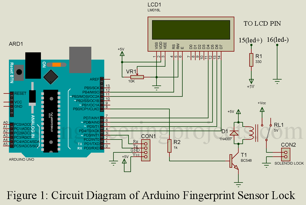
Arduino Uno MCU board is based on ATmega328/ATmega328P acts like a CPU of the system “Arduino Fingerprint Sensor Lock” the figure of which is shown in figure 1. This board comprises multiple features. There are 14 digital input/output (I/O) pins, six analogue inputs, 32k flash memory, 16MHz crystal oscillator, a USB connection, power jack, ICSP header and reset button. We can use any of its features through Arduino IDE software through proper programming.
(b). Fingerprint sensor module | Arduino Fingerprint Sensor Lock
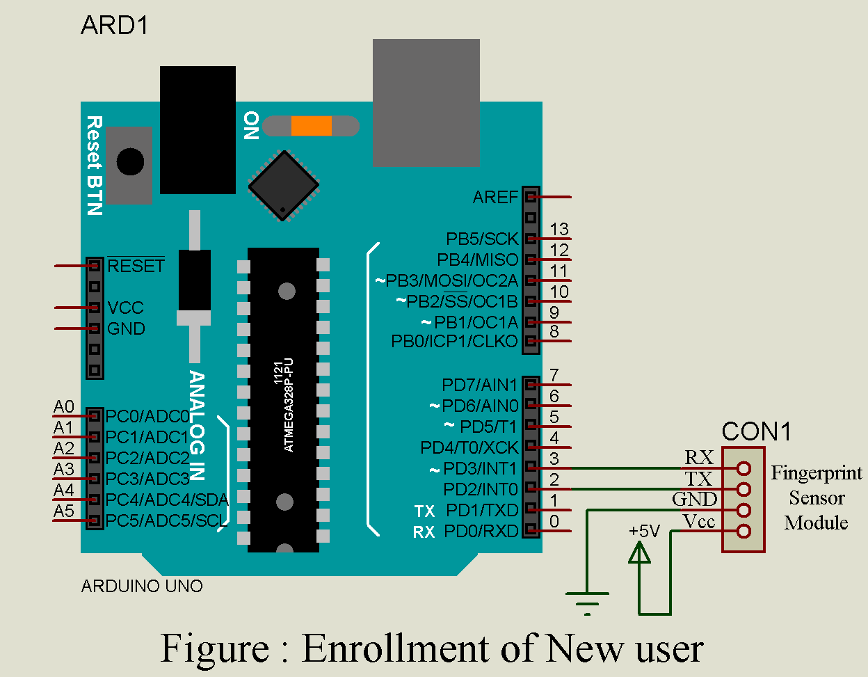
The RX and TX pin of fingerprint sensor module R305 is connected across D3 an D2 pin of arduino board respectively as shown in circuit diagram (figure 1). Since this module is constructed using UART technology, it is easy to interface sensor directly with the MCU or also to the PC using max232/USB serial adaptor. The information collected from the fingerprint can be collected in the module. During the process of identification, the data can be configured in either 1:1 or 1:N module. In order to ensure serial communication, two pins of R305 sensor; TX and RX are connected across digital pins 2 and 3 of Arduino Uno.
(c). LCD (Liquid Crystal Display) | Arduino Fingerprint Sensor Lock
The 16*2 LCD1 acts as a display media to distribute corresponding messages when the system is executed. In this type of particular IC, each character is made of 5×7 dot-matrix. The connection between LCD and Arduino Uno is done in following pattern:
- LCD pins 3, 4, 5 and 6 are configured in control mode and are linked to preset pin (VR1) as output, pin 12, GND and pin 11 of Arduino Uno.
- The four data pins of LCD; pins 11, 12, 13 and 14 are coupled to pins 7, 6, 5 and 4 of Arduino, respectively.
- The Preset VR1 is used to adjust the contrast of the LCD display.
(d). Electronic door-lock Solenoid | Arduino Fingerprint Sensor Lock
It is nothing new but almost similar to an electromagnet. A slug of metal i.e. armature surrounded by a big coil of copper wire forms a solenoid. It is connected to the output of relay as show in circuit diagram. The working of solenoid is much simpler than its construction, as soon as the coil gets energized; the armature is pulled into the center of the coil that permits the solenoid to move to one end.
Since the supply current required to operate the solenoid lock is higher than the supply form Arduino Uno board, we need to employ an extra 5V relay (RL1). In order to establish connection between normally open relay contacts and GND, solenoid is implemented in the middle. The figure illustrated in output (Fig: 2) depict the view on sequence of messages to be displayed on the LCD from author’s prototype.
Software of Arduino Fingerprint Sensor Lock
The core section of the project; software part utilizes two different programs-enroll and fingerprint. getFingerprintEnroll(int,id), Adafruit_Fingerprint(&mySerial) and getFingerprintEnroll(id) are some of the different functions syntax used in those programs. These are in-built functions found in library and they pass arguments when these functions are called at different locations of programs.
Once the enroll part of the program has been uploaded in the Arduino Uno, go through the Arduino IDE and then open the serial monitor by opening tabs like tools and then select serial monitor options. It is necessary to set the baud rate to a value lower than the serial monitor window to 38400. At the same time choose Newline option.
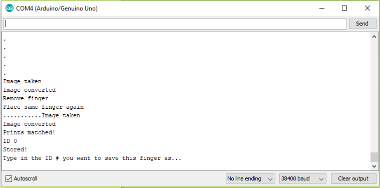
And now, one by one execute the instructions given on the serial monitor. Once you place a finger on the fingerprint module, type an ID number. It can be any whole number. Then when send key is entered, the corresponding ID number is transmitted to the main portion i.e. Arduino Uno form the serial monitor section. Thus sent information (fingerprint) is digitized and converted into storable form which is piled up in R305 module database.
This system can withstand a total of 200+ fingerprints which is remarkable. However, each fingerprint must have unique ID number assigned since this is the prime factor to be utilized in identification of the valid individual’s name. The serial monitor assists the client in an effective way. Every real-time information of when to place the finger on the sensing module and when it is okay to remove, is all provided by the serial monitor which makes this project more user-friendly.
If you prefer to debug the system without implementing LCD display, initially upload the fingerprint program and then set the same settings as mentioned above for the serial monitor configuration. Here again the serial monitor performs the guide function. This technique of implementing circuit is employed to make necessary comparisons between the current sensed fingerprint sample with the samples already stored in the database. The programming flexibility feature permits customer to amend necessary changes in names and ID number by changing the code to a slight extent as per the requirement.
Construction and testing of Arduino Fingerprint Sensor Lock:-
The figure 3 and figure 4 reflect the actual-size of single-side PCB layout for the fingerprint door unlock system and its component layout respectively. To make this circuit more reliable and convenient, the design of PCB has been done as an Arduino Shield. Based on the requirements from the customer, further changes in the project can be done. To check if the PCB will work fine, a cable connector is used to perform test actions when connected with the Arduino.

Figure 2: Solder Side PCB Diagram or arduino fingerprint scanner lock
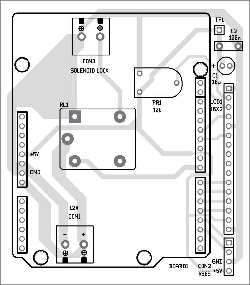
Figure 3: Component Side PCB Diagram of Arduino Fingerprint Scanner Lock
One must be careful to ensure that the baud rate value listed in the program must be accurate. It’s value does not affect the serial monitor but for sensitive device like R305 sensor, it must be precisely the value listed in the datasheet. However, this value may depend on the type of sensor used in the project. In the main code, this values are fed in the system as Serial.begin(38400) which represents the baud rate for serial monitor and finger.begin(57600) which represent the baud rate for sensor. The Arduino board must be reset beforehand to avoid any possible errors during validation of fingerprint.
Click Here To Download Software Code
PARTS LIST OF ARDUINO FINGERPRINT SCANNER LOCK
| Resistor (all ¼-watt, ± 5% Carbon) |
| R1 = 330Ω
R2 = 1 KΩ VR1 = 10 KΩ |
| Semiconductors |
| Arduino Uno Board
T1 = BC458 R305 Fingerprint Sensor module |
| Miscellaneous |
| LCD1 = 16*2 Alphanumeric LCD
RL1 = 5V 1C/O relay |
Procedure for Configuring Arduino Fingerprint Sensor Lock
- Download the software code folder from above link.
- Put the Library file in your Arduino IDE Library Folder of your computer.
- Assemble the enrollment new user circuit shown below.
- Upload the enroll.ino code to your arduino board.

- Open the serial monitor either from menu or by pressing Ctrl+Shift+m key at once.
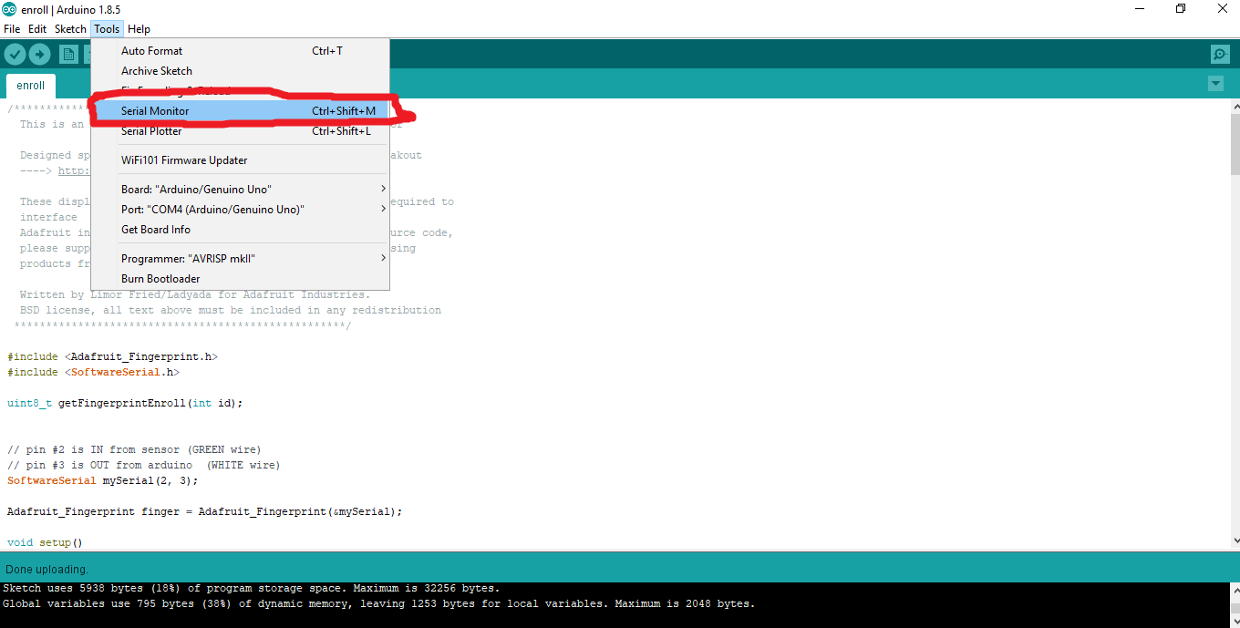
- Adjust the Baud rate to 38400 as shown in figure below.

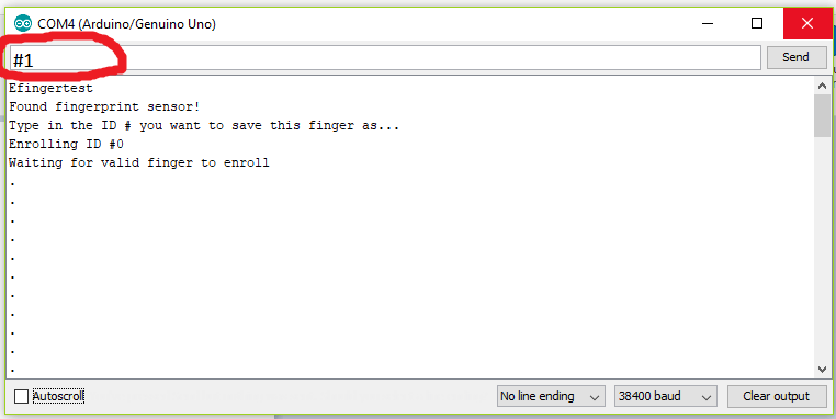
- Enter the enroll ID followed by # (eg. #1), Put the finger on finger print sensor module and follow the instruction shown in serial monitor.
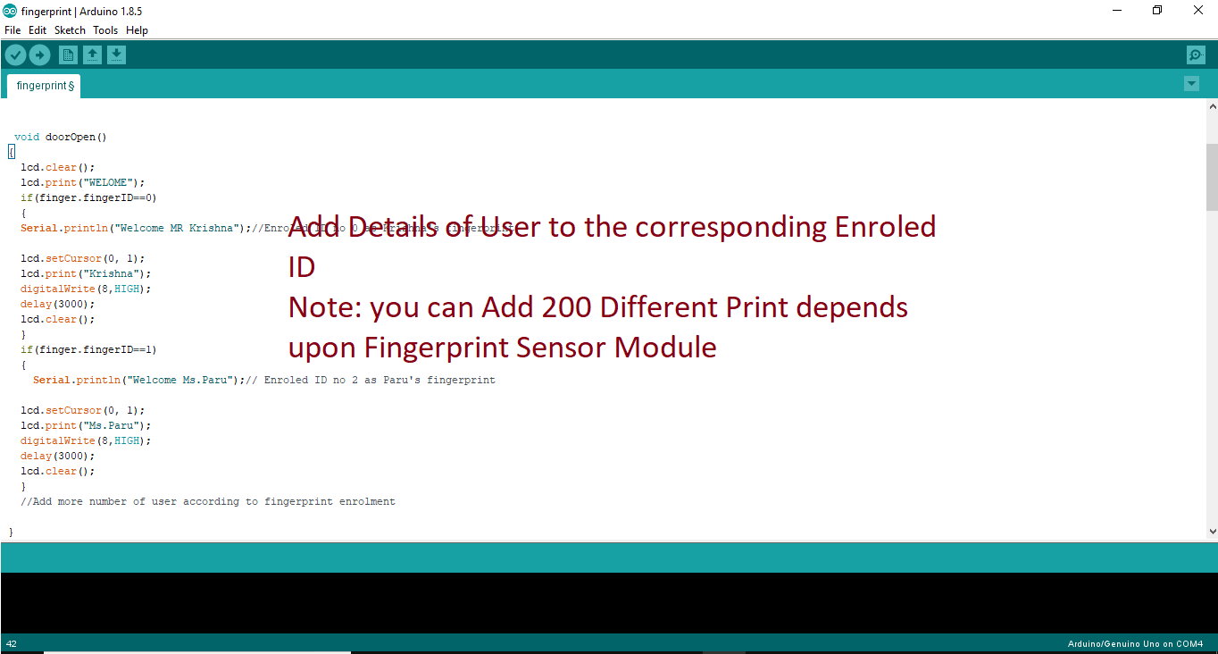
- Open fingerprint.ino from the software folder and assign the user to their corresponding ID in your source code (door open function) and upload it to your arduino board.
- Assemble the entire circuit shown in figure 1 (Circuit Diagram of Arduino Fingerprint Sensor Lock) and your device will be ready to use.


Hey good day sir! I just wanna ask about your project, the fingerprint sensor lock. I wanna know how to make it a fingerprint on off switch only. I want it to be an on/off switch for my project. Hoping for your quickest answer. Thanks sir!
you can connect any appliance like motor etc. instead of lock and it will work.
In-fact the circuit posted above is basically a switch (bio-metric switch) which is operated by scanning finger.
How VO is connected to VR1. Not understood. Please reply fast.
the wiper of VR1 (variable resistor) is connect to VO pin (pin 3) of LCD in order to control display contrast.
sir can u pls provide me the source code required for the project.its very urgent ,can you pls post it here or mail to my id [email protected]
the circuit posted here is simply switching circuit. You don’t need to modify anything (i.e. circuit and software) simply connect the electric gadget at the output (to the output of relay). If you know the method of using relay as switch it would be very simple for you.
my fingerprint module is r303a , so will there be any change in the above source code?
The code will be the same but pin configuration will be done if necessary.
Hello sir! I’m doing a bio-metric switch with a relay. It can be used within the LCD, is it possible to see the menu in the screen of your comptuer?
Sorry i did not get the point. What types of menu you want to display in computer?
Thank you sir
Project is 100% working,
And great thing about this article is PCB parts, though i wish to design a fingerprint sensor lock but by using jumper it seems wired. finally i found PCB and it would be very much easy to assemble.